In the previous post I said a couple of days more in the garage would have the electrical system finished and possibly spark on the plugs... Well, that is kind of true but it involved a weekend of puzzlement and deep pondering over electrical circuits in general and this ignition system in particular. Nothing comes easy on this restoration. Part due to the nature of the work and part due to personal shortcomings. Here´s the story:
 I really don´t like doing electrics and ignition systems. I suck at it, big time.
So, better start out easy and try to find out which breaker point serves which cylinder.
There are three of them, of course. Red, White and Brown leads from the points that connects to the respective ignition coil up at the steering head.
 Rotating the engine in its direction of rotation reveals the firing order when looking down at the top of each piston through the spark plug hole.
The direction of rotation is easily found by putting the engine in gear and slightly rolling the rear wheel in the correct direction and observing how the engine turns at the ignition timing plate.
Counter clock wise.
When one of the pistons reaches its TDC (Top Dead Center) you simply look at the timing plate and find out which breaker point is about to, or just opened.
 OK, the Red lead was for the Left cylinder, the Brown one for the Center and the White for the Right one.
First step was simply completed when the leads were connected to its respective coil.
Since the coils are all NOS I figured I could keep the brown supply lines intact on the coils and just replace the color coded ones with my breaker point leads. Easy enough!
 Next was getting the timing correct. The manual says 3,45 mm Before TDC or 25 degrees of rotation. I don´t have any tuning protractor but I do have a TDC measuring tool.
This device is screwed into the spark plug hole and easily finds the exact TDC and also 3,45 mm BTDC.
Here´s how you do it.
Unscrew the measuring tool at least 3,45 mm (there´s a micrometer scale on it), find TDC by rotation the engine back and forth just around the TDC and fasten the pin of the tool exactly at TDC.
Turn the engine far enough backwards, turn the micrometer scale back in exactly 3,45 mm into the tool and keep it there.
Now, rotate the engine slowly, in the direction of rotation until the piston hits the measuring tool. This is the point (3,45 mm BTDC) the breaker point is supposed to start opening, IE the spark plug sparks!
 It is also the point where you set the ignition timing index. On the left here this is done and as you can see it aligns pretty good with the Left cylinder index. That is excellent since I had the tool in the left cylinder. This was one of the things that had me worried using H1B components. Luckily I managed to find the correct ignition cam and the correct timing cam plate for the H1R. Otherwise this could have been more of a nightmare than it was.
 This is where I had made the first mistake. I had previously adjusted the breaker points so the cams were resting on the rotating ignition cam.
Wrong.
That made the timing impossible to get right. The opening of the points were way too big and that also threw the timing out the window.
I had to start with the breaker point opening....
0,3-0,4 mm. That meant I had to rotate the engine and set each point so the maximum opening ended up at, or close to, the 0,35 mm I was aiming for.
 With that adjustment done I was able to correctly time the left cylinder by turning the complete ignition plate so the breaker points start to open exactly when the left piston hits 3,45 mm Before Top Dead Center.
A nice gimmick to get this absolutely right is to have an old transistor radio in the garage playing. When the points open and the current flows through the coil there is a distinctive sound over the radio, at least if your ignition system isn´t shielded for radio interference. And I´m pretty sure this system is not.
In this case I started in the wrong end and had no electrical wiring at all so no current on the coils. Maybe next time.
 The timing of the Center and Right cylinder is made in a similar way, only now you don´t need the TDC-tool. You merely use the index, align the next cylinder and adjust the points to open exactly when the index hits then pointer. The Center and Right breaker points are individually adjusted via their mounting plates on the timing plate.
To make sure Ebbe got the crank perfectly mounted with 120 degrees separation between the cylinders I checked the 3,45 mm BTDC on the Center and Right cylinders as well. Better safe than sorry!
In order to get this 100% correct it is a good idea to do a dynamic check using an ignition timing stroboscope when the engine is running. Maybe later...
 No spark without electrical wiring. Next was getting the components connected and wiring drawn.
I have had some bad experiences with poor ground messing things up trying to start several bikes over the years. Better do it right this time.
The rectifier (on the right in the picture) is supposed to be grounded at the mounting point. I couldn´t be sure the front cowling stay (the "spear") was grounded good enough through the mounting bolts. Paint can be a pain when it comes to grounding components.
The regulator, on the left in the picture, doesn´t need to be grounded so no need for any extra wires there.
 So, I made an extra ground wire to be sure. This is the "spear" mounting screw with the new ground wire connected to it. In the last picture you could see the other end on top of the rectifier.
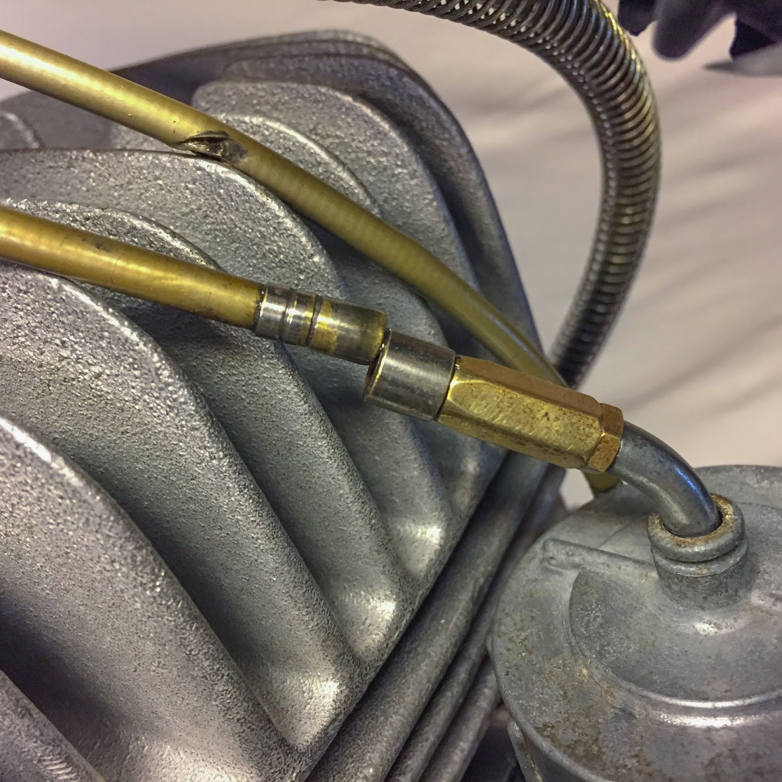
In this picture we can see the ignition coil and the fastener for the high tension cord. On H2:s the high tension cords are built-in with the coils, but here they are replaceable. I do have a plan for what kind of cords to use. We´ll talk about that later on.
 Connecting the components here was actually quite easy. Color coding worked to 90% and the last 10% was easily found out via the wiring diagram in the manual.
The Brown one from the regulator and the Red one from the rectifier shall both be connected to the Ignition switch. The rectifier, Red one, hot wired to the battery and the regulator, Brown one, over the ignition switch.
 Three Brown wires from the ignition coils together with the Brown one from the regulator to the switched side of the ignition switch.
It took some figuring out how to do this the best way. I though I had some nice three-way-bullet-connectors in stock, but no, I did not. Better get creative, then...
 If you have the correct parts and tools, making wiring is actually quite a bit of fun, once you have figured out how to connect the parts smartest.
On the left here is the female connector crimped to the wire. These "bullet" connectors are used on all Japanese bikes and are readily available at many venues over the internet.
 Next is the shrink tubing. This seals the connector from the elements and keeps water and dirt off the crimped part.
 Finally the protective transparent rubber cover is attached and the connection is done!
Easy peasy.
 Since I didn´t have any three-way connectors I fixed it another way. Two wires in to one bullet connector. Not optimal, but it´ll work out fine.
 That looks good enough for me. The objective here was simply to get current from the ignition switch to the coils and regulator. Done!
 That completes the switched side of the circuit. A bit of shrink tubing and another bullet connector slightly modified to fit the ignition switch and it was time to move on to the unswitched side of the system.
 That was easily done. I merely had to pull a wire from the battery to the switch and connect another lead to the "hot wired" rectifier.
Electrical system connected and built. Will I ever dare to connect a battery and flip the switch? That, my friends, is a completely different ballgame....
 I mentioned the high tension cords earlier. My plan was to use the ones supplied with the H1B coils. They are NOS, they are Kawasaki original spec products and I believed they would fit. They also have these nice "L", "R" and "C" labels on them. Seems like a nice touch. The only problem was that one of them, the "C" one was way too short.
On the H1B the coils are all mounted under the tank and the center coil is fastened right above the center spark plug. On the H1R the center coil is mounted far up front on the "spear". I had to use another cord temporarily. In the meantime eBay was consulted and a brand new H1B/A7/A1 high tension cord was located and bought from Wisconsin, USA.
 At this point I had been working on the bike a full day doing lots of other stuff as well, but I couldn´t resist testing the electrical system and check for spark. In retrospect I should have waited and thought things through a bit more...
 Connecting the system to a battery was easy enough. A well charged Z1 battery would most certainly do.
These flimsy "jumper cables" will be fine. There´s no starter here that needs a big amp output so this will work.
 And the connections at the battery box. Better check carefully that the plus terminal doesn´t come in contact with the frame or the negative terminal. We don´t want any short circuits here!
Really nervous when I pushed the switch in to switch the ignition "ON". Would it blow the fuse, start a fire somewhere?
No, nothing happened, and that´s good! Now, A gentle spin on the rear wheel... Nothing.
No spark, no sound, no nothing!
GAH!! I knew this would happen... Well, I pulled the switch out and for some reason tried spinning the rear wheel. Sparks on all three! What??
 I measured and checked everything over and over and came to the conclusion that I did have spark on the system when the ignition switch was turned off and there was no current on the coils...
I was tired, it was the last night before going off to work so I decided to leave it right there. I needed time to think this through and look carefully at the electrical wiring systems for the H1R and the H1B.
OK, happy to have spark? You bet! But why when the switch was off....?? I had some thinking to do during the weekend I was off working.
 I have the H1R wiring diagram in my iPad and brought that to work to think things over. How hard can it be?
I had done all connections according the schematic and still that strange phenomena.
Could it be something different with the H1B coils versus the H1R:s?
It is simple enough to see that the coils need current on the positive terminal through the ignition switch. How does it look on the H1B diagram?
 More or less identical diagrams apart from the fact that the street bikes have lots of other things going on in the system, like lights, more complicated ignition switch, turn signals and brake lights etc, etc... But the similarities concerning the regulator, rectifier and the current to the coils are very real. Looking at these schematics throughout that weekend was driving me more or less crazy.
Finally I realized I must have gotten it all wrong there, that late night, being tired and over enthusiastic having completed the electric system.
 The first thing I did after returning from work was hitting the garage and checking the ignition switch...
Yeah, You guessed it. The switch is "ON" when pulled out and "OFF" pushed in.
In my deranged state of mind that late evening I made many mistakes including the wonderful achievement to get a simple voltage check over a circuit breaker all wrong ending up spending a full weekend thinking over something that was correct all the time. Thankfully I didn´t do something stupid, just left it on the lift and went to work...
 A few days later the long high tension cord arrived and I could replace the temporary one with a more original looking cord.
Seen here on the right with the "C" label waiting to be attached. Those NGK spark plug caps will have to do for now. The original H1R (21130-015) are, of course, impossible to find. I do have a plan for something more stock looking, though.
 Now that the wiring was all done it was time to put the wiring loom in place on the frame. As I said earlier, the loom is rather long and I had to make a loop of it as it exits the ignition cover. My plan was to pull it up under the carburetor, over the chain cover and then up towards the steering head. Not good.
It had to be like this in the picture on the left. Looking at old pictures and photos of other H1R:s around the world I found that this is the way they are mounted. You can also see the black lead on the frame tube going to the battery.
 I had a couple of options regarding fastening the wire loom to the frame. I had some stock wire loom bands used on the H2:s and the older rubber type used on the A1/A7:s and real early H1:s. None of them looked right. In old pics it looks like it is simply taped with electric tape to the frame. Easy enough, but I couldn´t have it that way.
The solution? Vulcanizing tape!
A wonderful product I have used on many occasions through the years. It looks like simple electric tape but forms a solid rubber tube when stretched about 50% and then applied in as many layers you need. It is even possible to fabricate O-rings with this stuff. I think its main purpose is repairing cooling tubes on automotive applications etc.
 I replaced the electric tape on the loom exiting through the ignition cover. Much tighter and a better seal than the ordinary tape.
 To the right here I´m making the rubber fasteners for the loom. The loom sits on the inside of the tubing and 4-5 turns with the vulc tape stretched to approx 50% got it done!
 I think it looks very genuine and a bit like that flimsy electric tape from the old days. I feel a lot better about this method though. It won´t come off easily!
I think I´ll replace also the H2 bands holding the battery lead. I´ll fix that later on.
 What else needs fixing?
The front brake... I never adjusted it properly, merely put it together.
I was planning to safe-wire these screws holding the front brake torque arm to the brake plate. Janne had some nice lock washers handy so why not? Lets try them on.
As you can see they needed some adjustment also. Tab too wide and hole too small. I think they are original on the Yamaha TZ:s and they obviously use 8mm screws and Kawasaki 10mm.
 Well, not too difficult modification to do. Cutting the tab and filing the hole up a bit. The drilled hole in the screw head tells it used to be safe-wired before. For now, I´ll go with this solution. I think it looks better than the wire.
 Finished! Except for the final bending of the washer to the screw head. Well, you know by now, I always do everything at least two times... Better leave that to the very end of the build when all is done and tested.
 Adjusting the front brake is done in a couple of different steps. The idea here is to have both brake linings on each side touch the drum simultaneously. Each lining on each side is moved by one brake lever on the brake panel. They are connected with an adjustable rod. The method is simple enough.
Adjust the connecting rod as short as possible to make sure the rear brake lining doesn´t touch the drum when the large lever is pulled by the brake handle up on the handle bar.
On the left here I have adjusted the connecting rod. notice the difference in angle between the large and the small lever. It is quite clear that the rear (small) lever will not move the lining towards the drum before the large one.
The next steps require the possibility to rotate the wheel freely. Ok, I´ll have to fix that first!
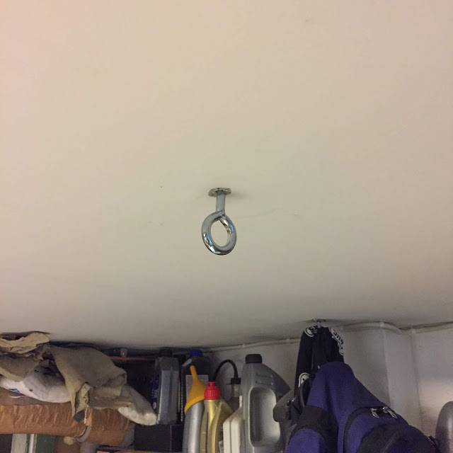 Tricky one... I couldn´t use a jack under the engine since I already had the exhaust on (see my point about always doing things at least two times....!!)
I ended up putting a large hook up on the ceiling. Thankfully I had noted where I have the beams under the drywall ceiling...
 A perfect fit right above the steering head. A ratchet tie-down and up the front end went!
Here it is hanging from the ceiling and resting on the stand on the foot pegs. Worked like a charm!
I must share this video of the front wheel spinning freely...
Imagine it is a 50 year old wheel. I think it spins very nice. The slight wobble seen on the tire is probably due to the tire being empty. I´ll check up on that later when I´ve filled it up.
 The adjustment starts with the large lever on the plate, the one actuated via the brake cable. I started out with unscrewing the brake cable adjuster until the front brake ling started touching the drum. Then backed of until the wheel could spin freely again.
 Next was the small lever (rear brake lining).
Wile slowly spinning the wheel you adjust the connecting rod until the rear ling touches the drum. In this position the rear lining will hit the drum first. Not good. Back it off until the wheel turns freely again.
Now you are close!
The final test is to pull the brake lever on the handle bar and check that both linings touch at the same time. This is done by carefully adjusting the connecting rod until the free play is gone on the rear (small) lever. It sounds complicated but it is rather straight forward when you think about it.
When your done on both sides, the slack in the brake cable won´t be too big and hopefully the adjuster up at the brake lever will be able to take it out with a margin to spare for adjusting the brake during riding with fading brakes..
 Time to get cracking with this friend again!
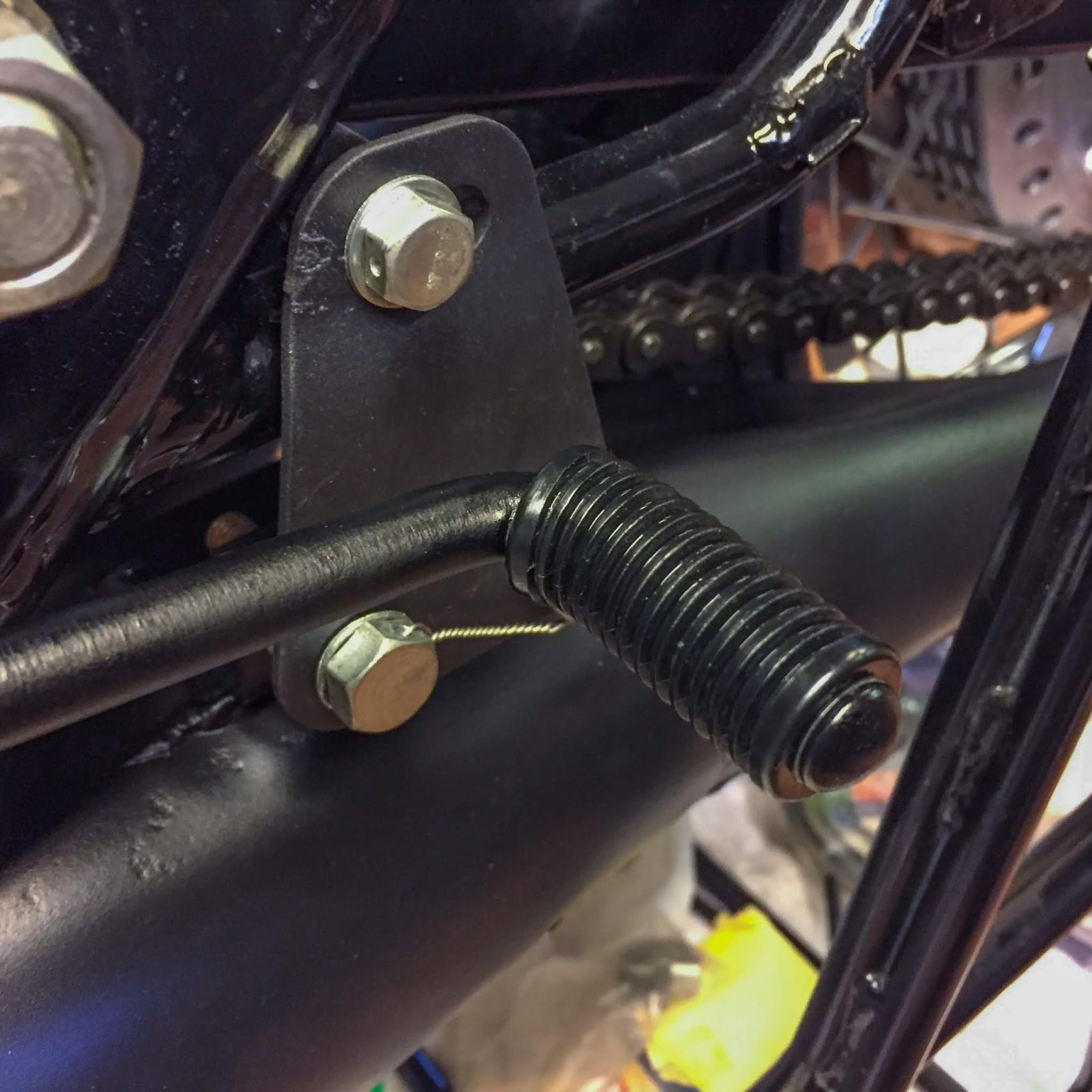
There are lots of fasteners to safe-wire on the front end of the bike.
I feel comfortable doing some of them now. Some I will save for later, until I´m positively certain that particular fastener will not have to be loosened again.
 The rear (small) brake lever on the left hand side brake plate.
 The large one, front left brake ling lever. Not perfect, but it´ll do...
 The left brake cable attachment to the adjuster on the brake plate.
 The steering head nut and screws. I´m kind of proud of this one... Three fasteners with one piece of wire. Ok, I know, it should have been tighter, but it´ll do for now!
 And the top triple tree pinch bolt. This was the last one this evening. I need more wire!
 It is "Bloody business" restoring old racing bikes...
I managed to hit my forehead on the rectifier bustling up and down adjusting the front brake and safety-wiring the front end. I didn´t notice it when it happened so this was a nice surprise when I looked in the mirror!
And that selfie, my friends, will be the end of this post. See you all next time!
Hopefully the aluminium tank is getting done soon at Alucars and maybe I can borrow Janne´s pit starter. Yeah, soon time for the first start attempt....
Stay safe and keep the front rubber on the asphalt.
Spring is finally here!
/Per

So, better start out easy and try to find out which breaker point serves which cylinder.
There are three of them, of course. Red, White and Brown leads from the points that connects to the respective ignition coil up at the steering head.

The direction of rotation is easily found by putting the engine in gear and slightly rolling the rear wheel in the correct direction and observing how the engine turns at the ignition timing plate.
Counter clock wise.
When one of the pistons reaches its TDC (Top Dead Center) you simply look at the timing plate and find out which breaker point is about to, or just opened.

First step was simply completed when the leads were connected to its respective coil.
Since the coils are all NOS I figured I could keep the brown supply lines intact on the coils and just replace the color coded ones with my breaker point leads. Easy enough!

This device is screwed into the spark plug hole and easily finds the exact TDC and also 3,45 mm BTDC.
Here´s how you do it.
Unscrew the measuring tool at least 3,45 mm (there´s a micrometer scale on it), find TDC by rotation the engine back and forth just around the TDC and fasten the pin of the tool exactly at TDC.
Turn the engine far enough backwards, turn the micrometer scale back in exactly 3,45 mm into the tool and keep it there.
Now, rotate the engine slowly, in the direction of rotation until the piston hits the measuring tool. This is the point (3,45 mm BTDC) the breaker point is supposed to start opening, IE the spark plug sparks!


Wrong.
That made the timing impossible to get right. The opening of the points were way too big and that also threw the timing out the window.
I had to start with the breaker point opening....
0,3-0,4 mm. That meant I had to rotate the engine and set each point so the maximum opening ended up at, or close to, the 0,35 mm I was aiming for.

A nice gimmick to get this absolutely right is to have an old transistor radio in the garage playing. When the points open and the current flows through the coil there is a distinctive sound over the radio, at least if your ignition system isn´t shielded for radio interference. And I´m pretty sure this system is not.
In this case I started in the wrong end and had no electrical wiring at all so no current on the coils. Maybe next time.

To make sure Ebbe got the crank perfectly mounted with 120 degrees separation between the cylinders I checked the 3,45 mm BTDC on the Center and Right cylinders as well. Better safe than sorry!
In order to get this 100% correct it is a good idea to do a dynamic check using an ignition timing stroboscope when the engine is running. Maybe later...

I have had some bad experiences with poor ground messing things up trying to start several bikes over the years. Better do it right this time.
The rectifier (on the right in the picture) is supposed to be grounded at the mounting point. I couldn´t be sure the front cowling stay (the "spear") was grounded good enough through the mounting bolts. Paint can be a pain when it comes to grounding components.
The regulator, on the left in the picture, doesn´t need to be grounded so no need for any extra wires there.

In this picture we can see the ignition coil and the fastener for the high tension cord. On H2:s the high tension cords are built-in with the coils, but here they are replaceable. I do have a plan for what kind of cords to use. We´ll talk about that later on.

The Brown one from the regulator and the Red one from the rectifier shall both be connected to the Ignition switch. The rectifier, Red one, hot wired to the battery and the regulator, Brown one, over the ignition switch.

It took some figuring out how to do this the best way. I though I had some nice three-way-bullet-connectors in stock, but no, I did not. Better get creative, then...

On the left here is the female connector crimped to the wire. These "bullet" connectors are used on all Japanese bikes and are readily available at many venues over the internet.


Easy peasy.


Electrical system connected and built. Will I ever dare to connect a battery and flip the switch? That, my friends, is a completely different ballgame....

On the H1B the coils are all mounted under the tank and the center coil is fastened right above the center spark plug. On the H1R the center coil is mounted far up front on the "spear". I had to use another cord temporarily. In the meantime eBay was consulted and a brand new H1B/A7/A1 high tension cord was located and bought from Wisconsin, USA.


These flimsy "jumper cables" will be fine. There´s no starter here that needs a big amp output so this will work.

Really nervous when I pushed the switch in to switch the ignition "ON". Would it blow the fuse, start a fire somewhere?
No, nothing happened, and that´s good! Now, A gentle spin on the rear wheel... Nothing.
No spark, no sound, no nothing!
GAH!! I knew this would happen... Well, I pulled the switch out and for some reason tried spinning the rear wheel. Sparks on all three! What??

I was tired, it was the last night before going off to work so I decided to leave it right there. I needed time to think this through and look carefully at the electrical wiring systems for the H1R and the H1B.
OK, happy to have spark? You bet! But why when the switch was off....?? I had some thinking to do during the weekend I was off working.

I had done all connections according the schematic and still that strange phenomena.
Could it be something different with the H1B coils versus the H1R:s?
It is simple enough to see that the coils need current on the positive terminal through the ignition switch. How does it look on the H1B diagram?

Finally I realized I must have gotten it all wrong there, that late night, being tired and over enthusiastic having completed the electric system.

Yeah, You guessed it. The switch is "ON" when pulled out and "OFF" pushed in.
In my deranged state of mind that late evening I made many mistakes including the wonderful achievement to get a simple voltage check over a circuit breaker all wrong ending up spending a full weekend thinking over something that was correct all the time. Thankfully I didn´t do something stupid, just left it on the lift and went to work...

Seen here on the right with the "C" label waiting to be attached. Those NGK spark plug caps will have to do for now. The original H1R (21130-015) are, of course, impossible to find. I do have a plan for something more stock looking, though.

It had to be like this in the picture on the left. Looking at old pictures and photos of other H1R:s around the world I found that this is the way they are mounted. You can also see the black lead on the frame tube going to the battery.

The solution? Vulcanizing tape!
A wonderful product I have used on many occasions through the years. It looks like simple electric tape but forms a solid rubber tube when stretched about 50% and then applied in as many layers you need. It is even possible to fabricate O-rings with this stuff. I think its main purpose is repairing cooling tubes on automotive applications etc.


I think I´ll replace also the H2 bands holding the battery lead. I´ll fix that later on.

The front brake... I never adjusted it properly, merely put it together.
I was planning to safe-wire these screws holding the front brake torque arm to the brake plate. Janne had some nice lock washers handy so why not? Lets try them on.
As you can see they needed some adjustment also. Tab too wide and hole too small. I think they are original on the Yamaha TZ:s and they obviously use 8mm screws and Kawasaki 10mm.


Adjust the connecting rod as short as possible to make sure the rear brake lining doesn´t touch the drum when the large lever is pulled by the brake handle up on the handle bar.
On the left here I have adjusted the connecting rod. notice the difference in angle between the large and the small lever. It is quite clear that the rear (small) lever will not move the lining towards the drum before the large one.
The next steps require the possibility to rotate the wheel freely. Ok, I´ll have to fix that first!

I ended up putting a large hook up on the ceiling. Thankfully I had noted where I have the beams under the drywall ceiling...

Here it is hanging from the ceiling and resting on the stand on the foot pegs. Worked like a charm!
I must share this video of the front wheel spinning freely...
Imagine it is a 50 year old wheel. I think it spins very nice. The slight wobble seen on the tire is probably due to the tire being empty. I´ll check up on that later when I´ve filled it up.


Wile slowly spinning the wheel you adjust the connecting rod until the rear ling touches the drum. In this position the rear lining will hit the drum first. Not good. Back it off until the wheel turns freely again.
Now you are close!
The final test is to pull the brake lever on the handle bar and check that both linings touch at the same time. This is done by carefully adjusting the connecting rod until the free play is gone on the rear (small) lever. It sounds complicated but it is rather straight forward when you think about it.
When your done on both sides, the slack in the brake cable won´t be too big and hopefully the adjuster up at the brake lever will be able to take it out with a margin to spare for adjusting the brake during riding with fading brakes..

There are lots of fasteners to safe-wire on the front end of the bike.
I feel comfortable doing some of them now. Some I will save for later, until I´m positively certain that particular fastener will not have to be loosened again.


I managed to hit my forehead on the rectifier bustling up and down adjusting the front brake and safety-wiring the front end. I didn´t notice it when it happened so this was a nice surprise when I looked in the mirror!
And that selfie, my friends, will be the end of this post. See you all next time!
Hopefully the aluminium tank is getting done soon at Alucars and maybe I can borrow Janne´s pit starter. Yeah, soon time for the first start attempt....
Stay safe and keep the front rubber on the asphalt.
Spring is finally here!
/Per