OK, back from a two-week vacation in Japan and Thailand and another two weeks being seriously sick and cold after coming home to wintery Sweden. Some more progress has been made on the racer project while I was away and also after coming home.
During my vacation I was thinking it would be real smart if Bert at Alucars would start out with the repair of the expansion chambers instead of building the aluminium tank. I need to continue working on the bike more than getting the tank ready for the start-up. I sent him an e- mail while on vacation and hoped he could change his schedule if he hadn´t started working on the tank already...
It turned out he is a very responsive person and when I gave him a call the day after our return home he had, of course, already finished the mufflers. I made the journey once more to Hällestad and collected the repaired pipes.
 There were two damages on the chambers I needed to get repaired. One was the straight part between the two cones on one of the pipes, seen here on the left. The other was a dented and bent stinger pipe on one of the other chambers.
 On the right here you can see the repair on the damaged chamber. The piece Bert cut out is standing up top right in the picture and is, as you can see, quite dented and ugly. the flat pieces of iron was used to keep the front and rear part of the muffler in place when Bert removed the middle part and had it replaced with new sheet metal.
He had a real hard time welding this material! The metal is thin, just 0.5-0.6mm thick and the inside totally covered in soot and unburnt two stroke oil. Those impurities on the inside caught fire all the time and made it extremely difficult to weld.
He ended up using his oldest welding equipment, the gas torch. That was the only way to control the melting adequately. Bert wasn´t to happy with the looks of the repair, but I´m happy with it! 100% better than before.
During the drive down to Bert I had been thinking about the next step in the restoration of the pipes. I would need some kind of heat resistant treatment done on them.

My plan initially was to have them painted with a heat resistant spray paint. Easy enough, but one problem is those paints need to be hardened in an oven at 200-250 degrees Celsius for an hour or two. I don´t have any oven large enough for these pipes. My sister, who is a Master of Pottery, has a couple of kilns, but they are not big enough either.
I called my powder coater and asked him if he could provide a heat resistant powder coating. Not possible, but his oven is large enough and can be pushed up to 250 degrees. We agreed I could get the spray cans, paint the mufflers and he would "bake" them in his oven. Super nice of him to offer that service!
Experience has taught me to always ask every stupid question you ever can come up with. So, I asked Bert.
"What kind of heat resistant treatment would you give these pipes?"
"Easy! There´s a guy far out in the Stockholm archipelago that offers ceramic coating on headers and exhaust parts for our racing cars. Ask him!"
 Perfect tip! As soon as I got back home I called "Leffe" at "Weird performance and coatings".
"Absolutely, I can do that for you"
Exactly what I wanted to hear! The next day I took the 1 hour drive straight eastward from Stockholm out in the archipelago on wintery, icy roads and delivered the three pipes and their fasteners for ceramic coating. It would be at least a week and a half he said... No biggie, just having a solution to that major problem made me feel great!
As you probably have figured out by now, these last pictures show me testing them on the bike before getting them coated. Just a small precaution to see to check they will fit perfectly also when restoration completed.
 The first picture shows the "cross-over-design" and that the pipes do fit into the cylinder spigots. The second shows the left side of the bike where the middle pipe goes out below the engine. Here on the left was the damaged stinger pipe, now straightened by Bert and still clear of the drive chain etc. Nice fitment and a superb repair!
 On the right here we can see the right side of the engine and the left pipe crossing over to the right side. The repair done to this pipe is visible beneath the engine. We can also see the brackets for the retaining springs welded to the forward part of the pipes.
 The clutch side with the mended chamber below the frame pipe. That repair Bert did will hardly be visible at all when everything is back on the bike. With the fairing in place it´ll be totally invisible! I feel very good and extremely relieved about it being fixed. The exhaust system was one of my major worries on this restoration and now it is coming back together very nicely.
 Here on the right we can see that the rear brake lever moves freely outside the bracket and bolts holding the pipe to the frame. That was one of the things that had me worrying. We´ll see if I can use those brackets or if I´ll have to manufacture new ones. The hole in the bracket seems a few mm off center towards the frame bracket. That problem might be solved by merely turning it around. Remains to be seen!
 The middle chamber is attached to the right one with this small bracket right next to the rear wheel. Fit like a charm! It was super nice to see that the pipes fit on the bike snug and tight. No worries then, getting them coated with that heat resistant ceramic coating.
 I saved the part of the chamber that Bert removed and replaced. I thought it would be fun to keep as a reminder what it looked like when I bought it. It is quite obvious I needed to have this part repaired when you see it now.
 When I left the tank in Hällestad I removed the fuel tap, remember?
Well, now was a good time to take a closer look at it. I never gave it much thought earlier, but I realized it might prove hard, even impossible, to find parts to restore it if it had rubber gaskets or seals in it.
It is clearly possible to take it apart if you look closer at it here on the left. There is a small retaining circlip inside the housing. The end of it protrudes in to the gap at "12 o´clock" above the lever. Let´s see what it looks like on the inside...
 The first step, getting the circlip loose. It is also very clearly visible here how "man-made" this petcock is. The casting is rather rough and all parts look like "one-offs" more or less. I imagine they made some 2-300 of these in 1970-71 and probably never made them again. I´ve heard of petcocks for these bikes selling for 1000-1200 $ US. With that in mind I need to get this one fixed and working.
 With the retaining clip off the lever, washer and spring came loos easily enough.
Good news! No rubber seal or gaskets so far. Those 4-holed-rubber gaskets used on the street bikes in their fuel petcocks are a big pain to fix. You buy new ones, install them and as you turn the lever the first time you cut your brand new rubber gasket to pieces. Shitty stuff. I don´t know how many stock street petcocks I have rebuilt over the years, using only NOS original parts, good repro parts or even the very best modern replacement-fuel-resistant-high-quality rubber parts... And they ALWAYS start to leak. Sooner or later. I think I have more than 10 used petcocks in stock, but always use the high flow Pingel replacement units on all my triple builds.
 Oh well, back to the H1R... In here was a nylon conical seal that turns with the lever and opens for the fuel to flow freely through the petcock. The only problem.... It was stuck. Always these stuck parts!
Since it was made of nylon I could use 5-56 or WD40 and try to free it. I didn´t want to use too much force here so once again. The torch.
 Real careful application of heat all over the petcock housing and never heating directly on the nylon part. 5-56 in the hole and letting it sit for a while did the trick.
 My largest screwdriver fit nicely in the slot in the nylon bushing and suddenly it turned. Free at last!
 Here are the parts that make up the fuel petcock. Housing, lever, spring (pushes the cone nylon bushing inwards), washer and the actual sealing cone. Next was getting the parts cleaned and polished for reassembly. Nice fettling for a change. Not too time consuming either since the parts are small and in overall very good condition.
 A peek inside the body. You can see the cone-shaped inner surface with its two holes. Cleanliness is a requirement in order to get this fuel tap leak proof. A thorough cleaning and light lubrication with automotive rubber grease was in order here. I sure hope I´ll be more lucky restoring this one compared to the street ones!
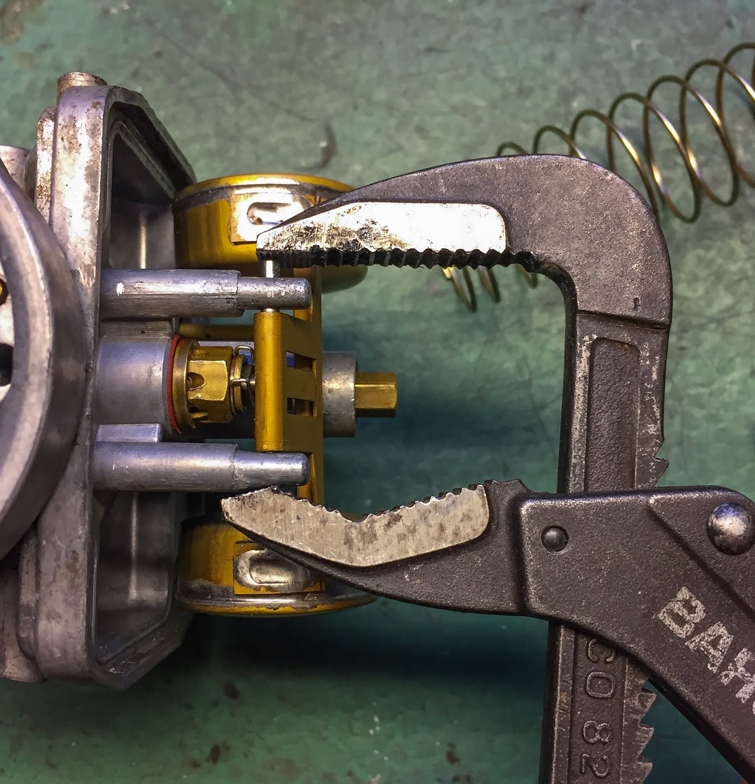
 Reassembly was quite straight-forward. Getting the parts inside the body in reverse order was easy enough. The tricky part was getting the circlip back in place. The spring pushed the whole thing outwards so I had to secure it with my largest, strongest clamp to keep the spring from pushing the parts out. Tricky stuff to get the clip in place without loosing the grip of the clamp.
 Finally I got it right. The fuel petcock is back in working order and hopefully not leaking.... The action on the lever is smooth and it seems to be working OK
A light polish by hand got the muck and dirt off it.Now it is ready to be put back on the tank as soon as it gets back home. I would say this is now a 1200$ fuel petcock!
One less thing to worry about! They are getting rather few these days, actually. The things I worry about. Feels very good!
 It took only 3 days... "Leffe" called me back on Saturday (I left the pipes with him on Wednesday...) and said they were done! Wow! 3 days instead of 1,5 week. I went there again last Sunday and picked them up.
What a wonderful job he did on those pipes! I am more than happy with the look of these babies. Exactly the right satin, semi-gloss black paint I was looking for. 3000:- SEK, approx 320 $ US is more than a fair price for this treatment. I can hereby strongly recommend "Weird Performance and coatings" east of Stockholm on the Värmdö island. Not only does Leffe provide excellent workmanship quicky and at a reasonable price, you also get a nice drive out into the Stockholm archipelago!
 After a break in working on the bike, working in real life, My next mission was to get those restored pipes back on the racer.
Before doing that I had to drill and safety wire all the engine bolts. The nuts were already drilled, but I changed the long retaining bolts for new ones. The ones on the bike at the time of purchase were of very different manufacture. A couple of them were even merely threaded iron bars.
So, I ruined a couple of drills in the process. One broke and two were dulled from my hand drilling.
 Remember I tried to learn the noble art of safe-tying a while back? Well, I still need a lot of training!
It sure got a lot easier thanks to my oldest friend from childhood, Finn, who saw my futile tries before and sent me a professional safety wiring plier/tool. Everyone knows that a good tool gets half the job done at once. The other half comes from training and knowledge. Now I have the correct tool....
 My wirings are getting better each time I try. A couple of weeks doing nothing but safety wiring together with some tuition might improve my game here considerably.
On the right is one of my first on the engine bolts. Looking at old pictures from the racing pits during the seventies I believe this is close to what they looked like from factory.
 Putting the wiring around the frame tubes seems to be way over the top, but I believe that´s what they did. The wiring is also supposed to "pull" in the correct direction, i.e tightening the bolt/nut. Sort of like I almost got it here on the left. At least it won´t loosen and that´s what counts.
 The tool is absolutely wonderful to work with.
It makes gorgeous windings on the wire and pulls it real tight and nice to the bolts and nuts unless you pull it too hard in your ambition to get it perfect.
This is what happened more than once. I broke the wire and had to do it all again. At least four times.
Well, with training, training and more training I might finally get it right.
 As the engine got safe-tied to the frame I began looking for the parts needed to attach the exhaust system to the engine. I know I have all six of the springs needed somewhere, but could only find five right now. No big deal, when I locate the sixth it´ll be an easy install. NOS parts are always NOS parts. And I love it!
 The brackets, springs, washers and bolts got back on their mounts. Pretty neat construction, actually, where there´s an adjustment possibility by tightening the screws and thus moving the pipe outwards in relation to the frame. Might prove to be important later on, I guess.
 A better view of the bracket and the other parts. All according the parts manual, of course. This time I turned it around for a better fitment of the bolt to the frame.
 The left side muffler is easiest to get in place, so I started out with that one. Here´s a picture of the bracket on that side.
You can see how neatly the chamber leaves space for the drive chain and the gear change pedal moves just outside the mounting bolts. These will, of course, be safe-tied later on as well.
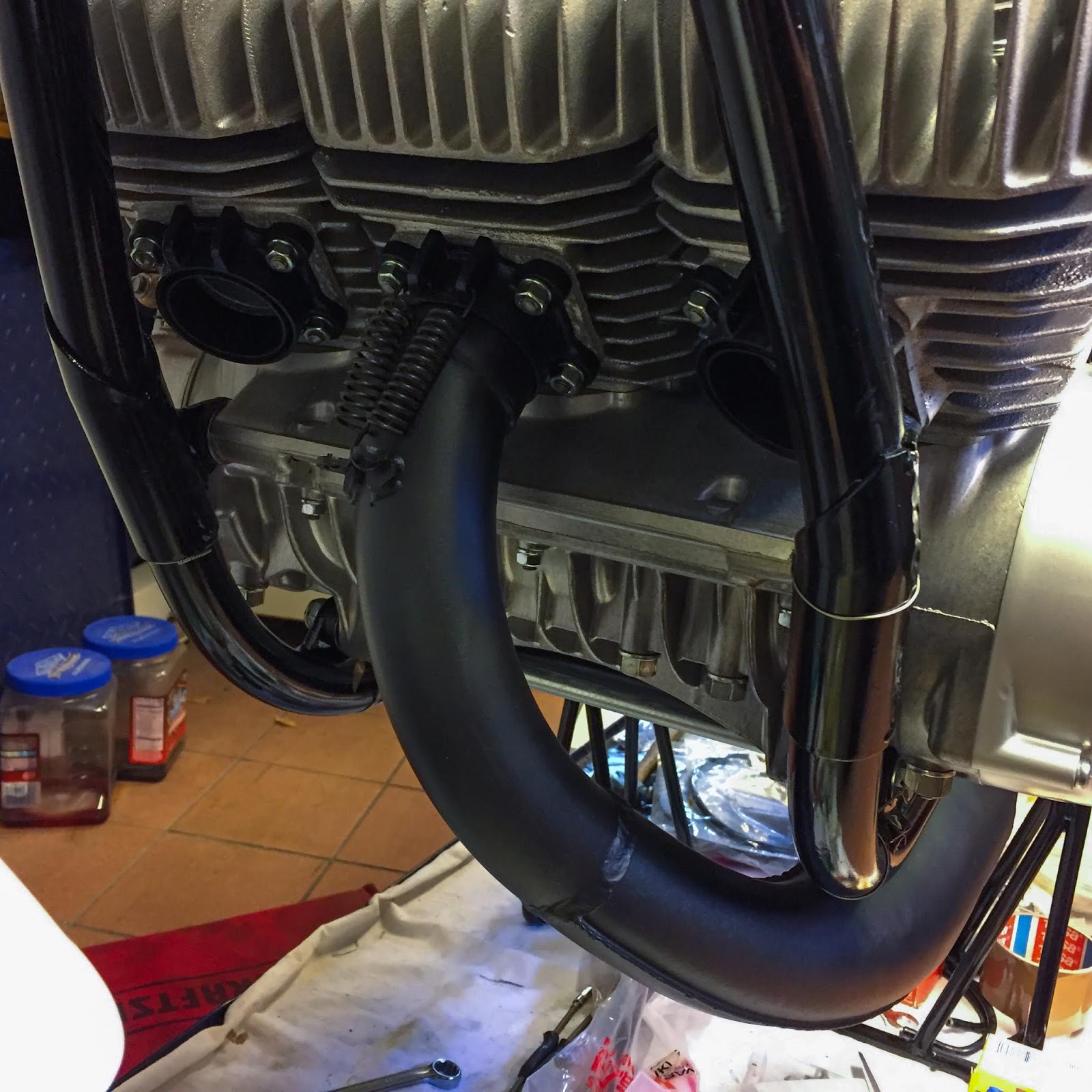
 Up front there´s two springs on each pipe holding it in place inside the cylinder spigot.
Here I could turn each spring two ways and, of course, I had to do it twice. This was the better-looking way. Not that it matters one bit, but my aesthetics told me to have it this way.
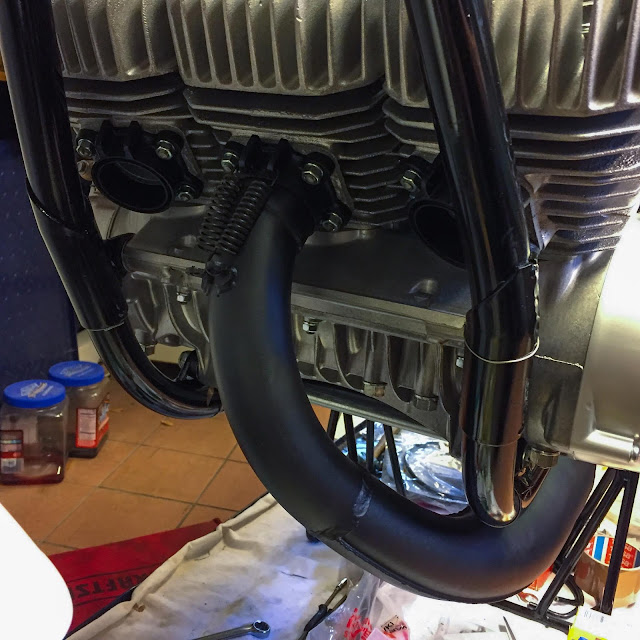 The very first pipe in place on the bike. Finally some real progress!
 Why not take the opportunity to safe-tie the swing bolt and nuts while I´m at it...?
For some reason they decided to go with the double-nut-safety-technique on this one. I guess, and that´s also the way I used it when tightening the swing arm, they wanted a certain torque on the nut. The only way to properly secure it without pulling it super tight to the frame is to "lock" it with another nut outside. They used the same technique on the rear fender nuts, remember?
 I´m quite proud of this one!
Safe-tie of double nuts to the frame by use of only one string of wire.
First I secured the outer nut to the inner one, in the correct direction and with good enough tension. After that I approximated the amount of wire needed for the long spiral and got it "Bang On". The trick is to estimate how much shorter the spiral will be in comparison to the unwinded wires before starting to pull the tool. And you need to have enough wire to go around the frame and make another winding to secure it.
Anyway, So happy with this one!
 On the left here you can see I thought it through before doing it. At least that´s what I would like to think.
I saved the safety-wire for the mounting bolt to the frame for later. I KNOW I´ll have to remove the pipe at least two more times before I´m done with it so better not safe-tie it just yet. Over precautious? Maybe, maybe not...
 Two in place! I´m really getting there now... One more to go. The most difficult.
 The two pipes on the right hand side of the bike hang together in a quite flimsy way. The left pipe, crossing over the other two, sits furthest to the right on the bike and also have the bracket for the frame welded to it. The inner (right pipe at the cylinders) is only attached to the cylinder and the retaining bracket on the stinger pipes at the rear.
I had to hang it temporarily at the foot rest before mounting the last pipe.
 Ready up front!
Quite a perfect fit here. They are free of each other and attach nicely to the cylinders. The last spring will be easy enough to fit when I find it!
 A somewhat tighter fit at the rear brake pedal and the right muffler mounting bracket.
Turning that bracket around was good! Now the bolt could enter the frame mounting easily enough without pushing the pipe out of the spigot up front.
 Here at the rear is the possibility to adjust the position of the inner pipe in relation to the outer ones. Depending on how you twist the bracket you move the middle pipe in-, or outwards. It is extremely difficult to fit these "fat" pipes without having them touch each other at all beneath the engione. We´ll see how well I succeeded when it is time to start it up.
 At least they are back on. Suddenly it looks a lot more like a racing bike.
I´m super happy the pipes were there at all. And now, as I see them back on here, all the efforts in restoring them were worth it!
I think they look the part here. Could have been used for a couple of races, got cleaned up and remounted on the bike. A small, but significant victory.
 Working this intensely on the bike makes my very well cleaned and extremely well equipped garage (well, maybe not so....) look like a war zone. Believe it or not, but things ARE organized in some mysterious way. I know in which of the plastic bowls to find screws etc and the piles are made in some kind of chronological order. The longer time that has passed since having something in my hand, the further down I have to look...
That wonderful safe-tying tool is right at the edge of the bench. A new favorite!
 The last picture for today shows the bike and its condition right now. Getting there!
Next up is the restoration of the electrical system and getting the cables back on. I should have done that long ago, but getting the pipes restored inspired me to get them back on the bike.
Electrics is something I´m nervous to do. Make a mistake and you can easily burn a component or two in the process. That is something that just can´t happen! Better be very careful and double check everything again and again.
More about that next time....
Tada!
/Per


He had a real hard time welding this material! The metal is thin, just 0.5-0.6mm thick and the inside totally covered in soot and unburnt two stroke oil. Those impurities on the inside caught fire all the time and made it extremely difficult to weld.
He ended up using his oldest welding equipment, the gas torch. That was the only way to control the melting adequately. Bert wasn´t to happy with the looks of the repair, but I´m happy with it! 100% better than before.
During the drive down to Bert I had been thinking about the next step in the restoration of the pipes. I would need some kind of heat resistant treatment done on them.

My plan initially was to have them painted with a heat resistant spray paint. Easy enough, but one problem is those paints need to be hardened in an oven at 200-250 degrees Celsius for an hour or two. I don´t have any oven large enough for these pipes. My sister, who is a Master of Pottery, has a couple of kilns, but they are not big enough either.
I called my powder coater and asked him if he could provide a heat resistant powder coating. Not possible, but his oven is large enough and can be pushed up to 250 degrees. We agreed I could get the spray cans, paint the mufflers and he would "bake" them in his oven. Super nice of him to offer that service!
Experience has taught me to always ask every stupid question you ever can come up with. So, I asked Bert.
"What kind of heat resistant treatment would you give these pipes?"
"Easy! There´s a guy far out in the Stockholm archipelago that offers ceramic coating on headers and exhaust parts for our racing cars. Ask him!"

"Absolutely, I can do that for you"
Exactly what I wanted to hear! The next day I took the 1 hour drive straight eastward from Stockholm out in the archipelago on wintery, icy roads and delivered the three pipes and their fasteners for ceramic coating. It would be at least a week and a half he said... No biggie, just having a solution to that major problem made me feel great!
As you probably have figured out by now, these last pictures show me testing them on the bike before getting them coated. Just a small precaution to see to check they will fit perfectly also when restoration completed.


Well, now was a good time to take a closer look at it. I never gave it much thought earlier, but I realized it might prove hard, even impossible, to find parts to restore it if it had rubber gaskets or seals in it.
It is clearly possible to take it apart if you look closer at it here on the left. There is a small retaining circlip inside the housing. The end of it protrudes in to the gap at "12 o´clock" above the lever. Let´s see what it looks like on the inside...


Good news! No rubber seal or gaskets so far. Those 4-holed-rubber gaskets used on the street bikes in their fuel petcocks are a big pain to fix. You buy new ones, install them and as you turn the lever the first time you cut your brand new rubber gasket to pieces. Shitty stuff. I don´t know how many stock street petcocks I have rebuilt over the years, using only NOS original parts, good repro parts or even the very best modern replacement-fuel-resistant-high-quality rubber parts... And they ALWAYS start to leak. Sooner or later. I think I have more than 10 used petcocks in stock, but always use the high flow Pingel replacement units on all my triple builds.

Since it was made of nylon I could use 5-56 or WD40 and try to free it. I didn´t want to use too much force here so once again. The torch.


A light polish by hand got the muck and dirt off it.Now it is ready to be put back on the tank as soon as it gets back home. I would say this is now a 1200$ fuel petcock!
One less thing to worry about! They are getting rather few these days, actually. The things I worry about. Feels very good!

What a wonderful job he did on those pipes! I am more than happy with the look of these babies. Exactly the right satin, semi-gloss black paint I was looking for. 3000:- SEK, approx 320 $ US is more than a fair price for this treatment. I can hereby strongly recommend "Weird Performance and coatings" east of Stockholm on the Värmdö island. Not only does Leffe provide excellent workmanship quicky and at a reasonable price, you also get a nice drive out into the Stockholm archipelago!

Before doing that I had to drill and safety wire all the engine bolts. The nuts were already drilled, but I changed the long retaining bolts for new ones. The ones on the bike at the time of purchase were of very different manufacture. A couple of them were even merely threaded iron bars.
So, I ruined a couple of drills in the process. One broke and two were dulled from my hand drilling.

It sure got a lot easier thanks to my oldest friend from childhood, Finn, who saw my futile tries before and sent me a professional safety wiring plier/tool. Everyone knows that a good tool gets half the job done at once. The other half comes from training and knowledge. Now I have the correct tool....

On the right is one of my first on the engine bolts. Looking at old pictures from the racing pits during the seventies I believe this is close to what they looked like from factory.


It makes gorgeous windings on the wire and pulls it real tight and nice to the bolts and nuts unless you pull it too hard in your ambition to get it perfect.
This is what happened more than once. I broke the wire and had to do it all again. At least four times.
Well, with training, training and more training I might finally get it right.


You can see how neatly the chamber leaves space for the drive chain and the gear change pedal moves just outside the mounting bolts. These will, of course, be safe-tied later on as well.

Here I could turn each spring two ways and, of course, I had to do it twice. This was the better-looking way. Not that it matters one bit, but my aesthetics told me to have it this way.

For some reason they decided to go with the double-nut-safety-technique on this one. I guess, and that´s also the way I used it when tightening the swing arm, they wanted a certain torque on the nut. The only way to properly secure it without pulling it super tight to the frame is to "lock" it with another nut outside. They used the same technique on the rear fender nuts, remember?

Safe-tie of double nuts to the frame by use of only one string of wire.
First I secured the outer nut to the inner one, in the correct direction and with good enough tension. After that I approximated the amount of wire needed for the long spiral and got it "Bang On". The trick is to estimate how much shorter the spiral will be in comparison to the unwinded wires before starting to pull the tool. And you need to have enough wire to go around the frame and make another winding to secure it.
Anyway, So happy with this one!

I saved the safety-wire for the mounting bolt to the frame for later. I KNOW I´ll have to remove the pipe at least two more times before I´m done with it so better not safe-tie it just yet. Over precautious? Maybe, maybe not...


I had to hang it temporarily at the foot rest before mounting the last pipe.

Quite a perfect fit here. They are free of each other and attach nicely to the cylinders. The last spring will be easy enough to fit when I find it!

Turning that bracket around was good! Now the bolt could enter the frame mounting easily enough without pushing the pipe out of the spigot up front.


I´m super happy the pipes were there at all. And now, as I see them back on here, all the efforts in restoring them were worth it!
I think they look the part here. Could have been used for a couple of races, got cleaned up and remounted on the bike. A small, but significant victory.

That wonderful safe-tying tool is right at the edge of the bench. A new favorite!

Next up is the restoration of the electrical system and getting the cables back on. I should have done that long ago, but getting the pipes restored inspired me to get them back on the bike.
Electrics is something I´m nervous to do. Make a mistake and you can easily burn a component or two in the process. That is something that just can´t happen! Better be very careful and double check everything again and again.
More about that next time....
Tada!
/Per