Having the ignition on the engine feels very good! Now I need to continue with the other electrics, wiring, cables, rear brake pedal adjustment screw and everything else... Lets start out with getting the coils and electric parts on at the front of the bike.
I´m still replacing the original ignition coils, 21121-037 with similar ones from the H1B 1972, 21121-054 and 21121-055, since I have not been able to find the original H1R coils....
 Now it was time to try and locate all parts needed. I had two regulators, one NOS and one very nice used. I chose the NOS one. Better safe than sorry when it comes to electric parts. Everything else in the picture to the left will be mounted on the "spear" up front where also the tachometer is mounted.
 The regulator and the rectifier mounted on the bracket that goes on to the "spear". Note how the regulator is rubber hinged, This is actually original also on the H1R. The rectifier is just screwed in place.
 The used rectifier turned out just fine after some cleaning. You can see the three diodes there, all in black, that turns alternating current in to direct current for the electrical system. The regulator keeps the voltage within limits not to overpower the electrical circuits. That one is a mechanical part that will not function properly when exposed to vibrations, hence the rubber mounting. There´s always a reason....
 Next was fixing the coils for mounting on the bike. The H1B uses a whole lot more stuff around the coils to keep them from vibrations and also weather. I don´t need any of it. They do have different part numbers in the catalogue but the actual coils are the same. The length of wiring and the different brackets make out the differences.
 I´ll probably not use the wiring on the coils but they can remain, the large rubber boots have to go, though. The same goes for the clamps. There´s no room under the steering head for that large double clamp. And that´s not the way it is supposed to look.
 To the right here is what´s going on the bike. Three H1B coils and the clamps from the Kröber coils plus that small, square, part that´ll work as a spacer for the two coils under the steering head. They have all been refurbished and rezinked. Sorry to say, even the correct H1R ignition coil clamps, 92037-052, are impossible to find... These will work fine, though.
 Three "Diamond" coils ready to be mounted to the racer. Note that the current feed lines are all brown and the others are color-coded to fit L,C and R cylinders on the H1B 1972.
 So far so good, The parts in place. The final fitment will probably be somewhat different so I´m not tightening the parts fully just yet. No safety wiring either since my experience tells me I´m going to change everything at least two or three times...
 Before putting these parts on I also had to straighten the "spear" a bit. I noticed it didn´t line up perfectly with the bike´s center line. Easy fix in my large vise. The rod is made from very thin-walled tubing and could easily be massaged straight. Without even ruining the paint. Thanks!
 Now for the wiring from the engine to the electrical "central" up front. I´m just trying to hook things up to get a feel for the length of the wiring and where to locate it when the time comes. Placement of the wiring is crucial on many bikes to be able to get room for all cables etc that need to pass close to the steering head. On Honda CBX:s there´s even a "wiring tracing diagram" to follow in order to get everything in place. No need for that here, though.
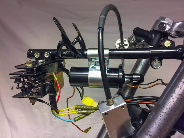
 Here I have managed to get the two front coils in place. I believe these two will be the left and right cylinder and the one up front will be the center one. That seems to make most sense here. Of course I had to move these further rear than I would like, but these coils might be a tad longer than the original ones and they ended up touching the frame tubes if not slided far to the rear in their clamps.
 A peek from below. There they are, snugly and tightly fitted without touching the frame. It really doesn´t matter that much since they are mounted solid to the frame anyhow. And that goes for the original coils as well. The principle is the same, just different coils and clamps. If you look closely you can see the color-coded cables coming out from the wiring. The ones with open connectors are the ones going to the different coils. I need to fit the wiring in a location where all coils can be connected without stretching the cables. It´s going to end up somewhere close to where it is right here!
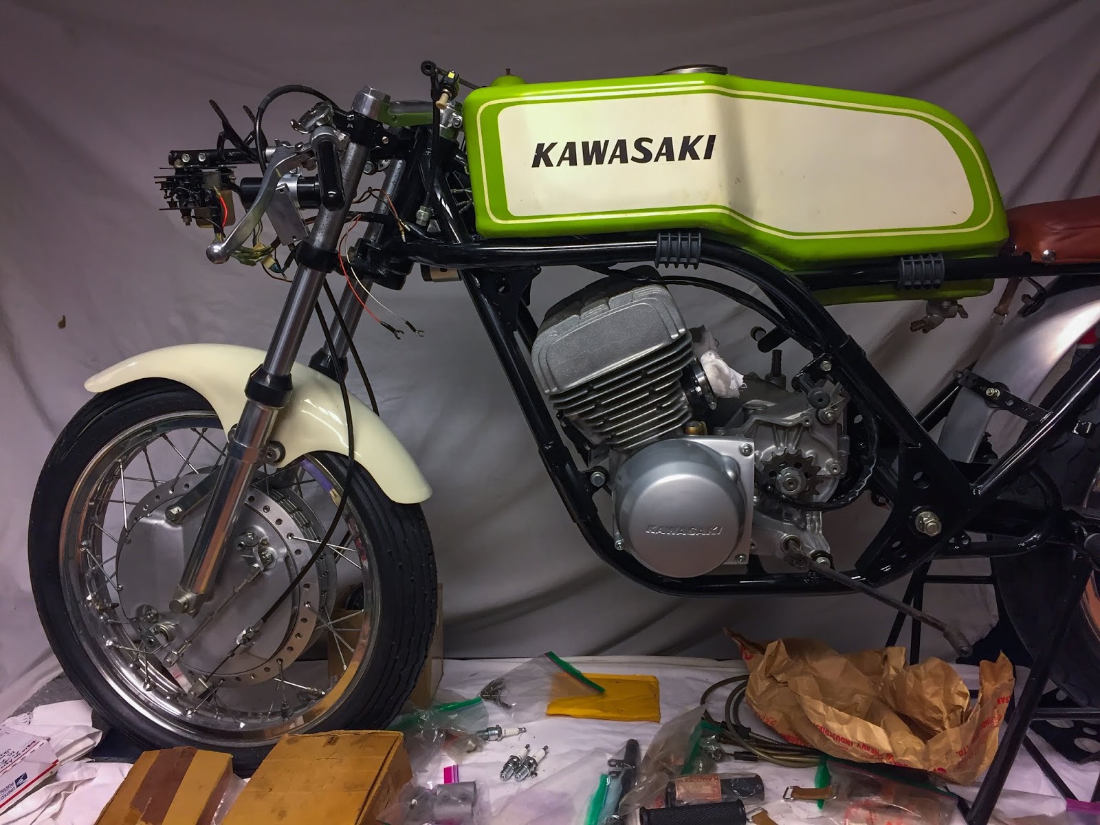
 Let´s try to fit the tank... Worked fine! I do believe the wiring will have to go on the outside of the frame tubing. We´ll see about that later when it´s time to put it on permanently. For now I can enjoy this view of the bike with some more electrics on!
 Time to move on to the drive chain. The problem with that was I had to get the clutch cable cleaned, lubricated and mounted on the clutch lever plus engine clutch release.
Here we go!
The H1R clutch cable has no adjuster midway between the engine and the handle bar as do the street bikes. I had a plan to replace my old, original one, with a very nice used street model clutch cable.
Two problems: it was too long and the adjuster would end up right where you can see it. Not good. A good clean and a pressure lube of the H1R cable had to do...
Here it is attached up at the clutch lever. I most often find it easier to fasten it at the lever first and then at the engine.
 And here´s the reason why you need to connect the clutch cable before putting the chain on.... When the chain is on, it is almost impossible to reach the clutch release and adjusting it.
Here it is attached AND correctly adjusted. When the release lever is resting at the approx 8 o´clock position with only minimal free play you´ve got it correct. Imagine where the force you pull on the cable with will do the most good. Yeah, at 9 o´clock, at a 90-degree angle.
If more play develops during driving you adjust at the handle bar lever until you have to get back down here and readjust at the release. Rather ingenious actually!
The video below shows how the clutch works. very cool to be able to see the action on a motorcycle clutch in real life! These babies are most often hidden behind engine covers and run in oil and can never be seen.. Nice!
 OK, the clutch is working. Drive chain up next. I bought a simple, non-O-ring, 530 DID chain. Of course it was way too long... It had to be cut to fit the bike. One would think, after all these years, I would have gotten myself a chain riveting/chain cutting tool. No, I did not. I do it the old fashioned way. First I need to measure how many links to remove. I find is easiest to measure on the rear sprocket. Be sure to have the wheel at its front-most position in the swing arm. Stretch the chain as hard as you can by hand and place the correct link next to the end link. be sure to get two "inner" links next to each other. If not, you´ll end up needing a "half link" to get the chain together. That is unnecessary in 95 % of the cases.
 Once you have decided where to cut the chain, mark that very rivet carefully and then grind it off with a grinder or Dremel toool. Then use a small mandrel and hammer to get the rivet out. And there you go! Chain cut to size...
 To the right you can see why it is important to cut the correct link. The chain lock goes in from behind and now the chain will stay in place all by itself.
 When the link cover is in place you put the chain lock clip in place with the opening facing away from the chain´s drive direction. This clip can later be secured in a couple of ways. I´ll most certainly use safety wiring. Many do use silicone to keep it from rattling loose, but I believe wiring was more commonly used during the day.
 Next up was getting the rear wheel permanently attached to the swing arm. I had to address the attachment of the rear brake cable at the wheel and rear brake pedal position adjustment screw.
To do this I had to get the bike off the stand and down on the floor. The rear brake pedal attaches to the right, rear foot rest and that had to come off to change the position of the screw.
To the right here, job is done!
I have the screw head below the bracket and the lock nut above. This way it worked out fine with the pedal at a good position adjustable up and down a bit.
 At the rear wheel everything is done now. Rear brake cable attached and adjusted, rear wheel adjusted in the swing arm for correct chain tension and line-up with the engine sprocket. I found a perfect size split pin for the rear axle nut, please note it isn´t fully installed yet, I will most certainly remove the wheel at least two or three times more before this is done...
 I also had to fix the bracket for the tachometer. Remember I had it refurbished a while ago with new rubber vulcanized to my original steel parts? It just had to be painted to go on the bike. Half an hour of masking and a rattle can spray of semi gloss wheel paint got that sorted. I have no problems using the slightly inferior spray colors from cans since the coats of paint on these bikes really are very thin and mostly without any primer at all. Well, here it is, drying over night.
 I have many small things I need to fix all over the place. The bracket for the "chain cover" was one of them. I measured the tube where it goes and bought a few different ones from eBay. the original part?
36024-003.. Yeah, been looking for ages.... No Joy! Here´s the one that was closest in diameter. 92037-1115. Muffler Clamp from KLT 250. I got two and modified one of them to fit my purposes.
 I had to make it a little smaller and change the direction of the bolt brackets a bit. The welded-on nut could remain, it looks the part! It was more or less perfect to just cut off the part with the bolt hole and then massage it back to the circular shape but with the correct diameter. Now it is also ready for paint.
 And here´s the chain guard with the clamp ready to go on the bike, once the clamp has been painted gloss black. I will also need to drill the hole in the front end of the guard. That end also has to be angled a bit... preferably before drilling. Those are all small, easy tasks that needs no bigger thought to be completed. Just some nice fettling in the garage.
That sums it all up for today! Work is ongoing now and progress is being made slowly but safely. It helps having 8 days off work here over Christmas and New Year... By the way, If I didn´t say it before:
HAPPY HOLIDAYS AND A HAPPY NEW YEAR TO YOU ALL!!
In 2019 this 1970 Kawasaki H1R will hopefully be done and up and running. Keep you fingers crossed!
/Per
I´m still replacing the original ignition coils, 21121-037 with similar ones from the H1B 1972, 21121-054 and 21121-055, since I have not been able to find the original H1R coils....


Here we go!
The H1R clutch cable has no adjuster midway between the engine and the handle bar as do the street bikes. I had a plan to replace my old, original one, with a very nice used street model clutch cable.
Two problems: it was too long and the adjuster would end up right where you can see it. Not good. A good clean and a pressure lube of the H1R cable had to do...
Here it is attached up at the clutch lever. I most often find it easier to fasten it at the lever first and then at the engine.

Here it is attached AND correctly adjusted. When the release lever is resting at the approx 8 o´clock position with only minimal free play you´ve got it correct. Imagine where the force you pull on the cable with will do the most good. Yeah, at 9 o´clock, at a 90-degree angle.
If more play develops during driving you adjust at the handle bar lever until you have to get back down here and readjust at the release. Rather ingenious actually!
The video below shows how the clutch works. very cool to be able to see the action on a motorcycle clutch in real life! These babies are most often hidden behind engine covers and run in oil and can never be seen.. Nice!


To do this I had to get the bike off the stand and down on the floor. The rear brake pedal attaches to the right, rear foot rest and that had to come off to change the position of the screw.
To the right here, job is done!
I have the screw head below the bracket and the lock nut above. This way it worked out fine with the pedal at a good position adjustable up and down a bit.


36024-003.. Yeah, been looking for ages.... No Joy! Here´s the one that was closest in diameter. 92037-1115. Muffler Clamp from KLT 250. I got two and modified one of them to fit my purposes.


That sums it all up for today! Work is ongoing now and progress is being made slowly but safely. It helps having 8 days off work here over Christmas and New Year... By the way, If I didn´t say it before:
HAPPY HOLIDAYS AND A HAPPY NEW YEAR TO YOU ALL!!
In 2019 this 1970 Kawasaki H1R will hopefully be done and up and running. Keep you fingers crossed!
/Per
Inga kommentarer:
Skicka en kommentar