It is always a great inspiration when the assembly of a bike has actually started. I´m lucky enough to have the bike and parts in my own home, just a staircase down, in the basement. That makes it so much easier to ramble down after dinner or just before bedtime and think about something or have a look at something bothering you or to just have a cold beer and enjoying the fact taht it is actually there in your own garage. Last time I got the lower triple tree and the swing arm in place and now it s time to continue with the top triple tree and a few other frame parts. Here we go!

The top yoke, or top triple tree, had to be cleaned and polished in some way. I decided to use my small buffing machine with a rather coarse grit to buff it up. This is really dirty work! You need to be prepared to vacuum your entire garage after each session at the wheel. The buffing spreads lint and dust all over the place.

Here it is, half finished. I probably went too far in shining up the surface, but that can be changed later on and it will change by itself unless I clear coat it. And that´s not going to happen here. A good, thick, layer of car wax protects the surface enough. Not too nice, remember?
The grit, or polishing compound, I use is something I bought at a swap meet years ago. Nothing fancy at all, but it works! I bought two different types, one coarse and one very fine. This is the coarse one...

I located the top bolt and the other bolts and put it all in place on top of the lower triple tree and here it is! Let´s move on to the rear fender.

This part has been clear coated, without a doubt. I thought about it for a while but decided against it for my part. The clear coats I´ve been able to acquire have never been good enough, so I usually leave the surface untouched when restored, but protected with car wax. Most often I use the old, very well known, Turtle green. Correct in time as well!
Anyway, the fender had to be cleaned and sanded. I planned to use some chemical stripper but was out of it at the time so there I was....

Elbow grease, sanding block and a little water now and then. Smaller and smaller grit on the paper/block until you´re happy with the surface. This one I won´t polish on the buffing wheel. I think it looks good in a little more satin finish.

Remember I discussed the originality of this fender in the beginning of the blog? Later bikes have a plastic fender and I thought mine might have been made by "Esso" or someone else during the time. Now, I´m quite convinced, it IS the original fender. Look at these edges. If someone would have made it during racing in the seventies I doubt they would have made it this good! The shape fits perfectly to the frame and also to the chain later on. I´m pretty sure this is the correct one. Not that it matters... It´s going back on anyway!

Here´s a little trick I thought of while sanding the fender. To get a bit more "factory made" appearance of the metal surface I sanded the edges of the fender in parallel strokes with the edges. This will make an impression of someone standing on a grinding/sanding machine polishing the surface at great pace and speed. I´ve seen these variations in grinding direction on NOS clutch covers etc on my older renovations. Just a gimmick, but let us see how it turned out!

Here´s the Turtle wax I was talking about earlier. The fender is sanded and polished to the shine I like it to have. Not too shiny and not too dull. Something in between. A thick layer of wax protects it...

And here is the finished result. Not restored to new condition, not too shiny... But nice enough to not look totally beaten up. I´ll also leave the marks after screws hitting the fender close to the edge on the right. They are part of it´s history. It might be the seat fasteners that have done those marks. We´ll see later when I put it on the frame. My gimmick with different directions of sanding is also clearly visible. I think I like it....

The same principle here. Dual nuts to lock the fender in place. I can understand why. The fender is mounted with rubber washers between the fender and the frame and also on the underside of the frame. There are no collars, though. Steel collars are used on street bikes in rubber mountings in order to be able to torque the nuts harder and still keep everything rubber mounted. This is another story. If I were to tighten these nuts hard, the rubber washers would be deformed and do no good at all. The trick here is to tighten the first nut just right for the rubber washer to keep its shape and then lock it all in place with the second nut. A modern way would be a nyloc nut, but we don´t want anything like that here, do we?!

I believe I got it about right... 6 nuts, 6 rubber washers and 3 rather large steel washers on the inside. Rear fender done!

Once again I couldn´t resist... Tank, seat and cover on the frame just to have a look... I like it!
The fender got the exact right "shine" and I feel no need to clear coat it at all.

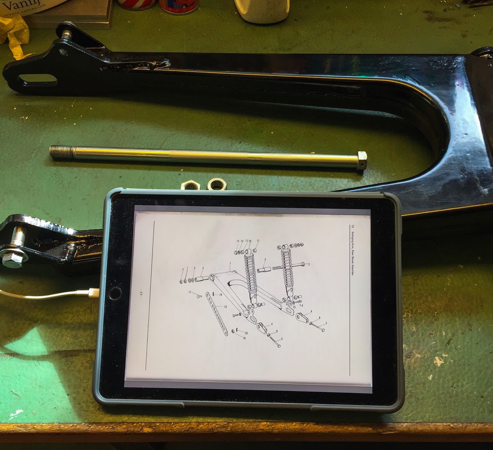
Time to move on to the front fork stanchions. I did manage to reproduce the inner tubes via purchasing a set of tubes for an old Yamaha RD250 1973-75 and having them modified to fit the H1R. That being done I´m still going to use my old, original, stanchions on the build. I do want to keep it as much the original bike as possible so they are going back on! Slightly pitted but straight and re chromed to specifications by a couple of great companies here in Stockholm. Look at the page from the parts manual! The dust boots are there as part numbers, but NOT the oil seals. Isn´t that odd? Were you supposed to replace the complete outer fork leg when the oil seal gave up? Well, it sure beats me... The dimensions are known and printed on the seals, so it wasn´t that hard to figure out the same oil seals used on the early H1:s would fit.
 Being a hoarder of old Kawasaki parts I had a number of these in stock, NOS. As you can see I treated the outer front fork tubes in the same manner as the top triple tree. Polished on the buffing wheel. The same reflection caught me here. A bit too shiny, but I´ll leave it as it is, for now.

Getting old oil seals out of fork tubes is generally a major pain in the... I have had to destroy many seals to get them out at all, often damaging the surface of the tube where the seal enters and sits. In this case it was a blast! It worked with my Oil seal removal tool from Craftsman! The steel bracket is there to avoid damage to the rim of the fork leg. Here you can also see the, slightly, too shiny surface of the outer leg.

The next step is cleaning and cleaning again of all parts going into the fork leg. These are all hydraulic parts that require extreme cleanliness to function the way we want them to. I tried to capture the inner surface of the outer front fork leg here to show how well polished it is. This is where the outer and inner front fork tubes meet and slide inside each other. Any dirt or foreign matter will make gouges and scratches on these parts. The hard chrome is hard, but not that hard... And this, inner surface of the outer tube, is all aluminium and very soft and vulnerable.

Next up is the mounting of the NOS oil seals. Here I prefer using a large socket that fits as close to the edge of the seal as possible without being caught inside the tube. Gently tapping all around it makes it enter and then be driven all the way down until it "bottoms out". Checking with the inspection mirror is an option also here.

The large washer and the circlip completes the oil seal mounting. A light coat of rubber grease on the lips of the oil seal makes it a lot easier to slide the outer tube on to the inner.

OK, time for the inner, hydraulic, parts. Same here. Clean, clean and clean again! These parts slide inside the inner tube and are held in place by a large circlip at the very end of the tube. Be very careful with the order of the parts. Follow the manual precisely to get it right. These principles are very valid when you´re working on you street bikes as well.

Here´s everyhting installed in the tube and ready to be secured by the circlip. Note how well they performed the hard chrome at "Fintlings" and also how nice the ground surface of the chrome is from B.L Slipteknik. Great job!!

The last step of the process before installing the spring, tube and washer is mating the inner and outer front fork tubes together. This is preferably done by an impact driver at a low torque setting and with a good fitting allen tool. I believe it is a 6mm allen screw and that can´t take too much pounding by the impact driver. There is a special tool from Kawasaki you can use to hold the hydraulic parts while securing the allen bolt, but this works as good!
In order to have the parts centered properly inside it is smart to have the tubes completely pushed together, "Bottomed out", so to speak when you use the impact driver. That way the hydraulic parts are centered and the outer and inner tubes can move freely. A splash of front fork oil on the parts during this process is a good idea to keep the polished surfaces intact.

So, here it is. One down, one to go!
Sliding on the dust boot and installing the spring, washer and tension tube is a no-brainer! Next time
I´ll be working on the front end some more and maybe installing two completely restored front fork legs to my slowly growing chassis. Tomorrow it´s off to work again.
C U in New York!
Over and out for now.....!!
/Per

The top yoke, or top triple tree, had to be cleaned and polished in some way. I decided to use my small buffing machine with a rather coarse grit to buff it up. This is really dirty work! You need to be prepared to vacuum your entire garage after each session at the wheel. The buffing spreads lint and dust all over the place.

Here it is, half finished. I probably went too far in shining up the surface, but that can be changed later on and it will change by itself unless I clear coat it. And that´s not going to happen here. A good, thick, layer of car wax protects the surface enough. Not too nice, remember?
The grit, or polishing compound, I use is something I bought at a swap meet years ago. Nothing fancy at all, but it works! I bought two different types, one coarse and one very fine. This is the coarse one...

I located the top bolt and the other bolts and put it all in place on top of the lower triple tree and here it is! Let´s move on to the rear fender.

This part has been clear coated, without a doubt. I thought about it for a while but decided against it for my part. The clear coats I´ve been able to acquire have never been good enough, so I usually leave the surface untouched when restored, but protected with car wax. Most often I use the old, very well known, Turtle green. Correct in time as well!
Anyway, the fender had to be cleaned and sanded. I planned to use some chemical stripper but was out of it at the time so there I was....

Elbow grease, sanding block and a little water now and then. Smaller and smaller grit on the paper/block until you´re happy with the surface. This one I won´t polish on the buffing wheel. I think it looks good in a little more satin finish.

Remember I discussed the originality of this fender in the beginning of the blog? Later bikes have a plastic fender and I thought mine might have been made by "Esso" or someone else during the time. Now, I´m quite convinced, it IS the original fender. Look at these edges. If someone would have made it during racing in the seventies I doubt they would have made it this good! The shape fits perfectly to the frame and also to the chain later on. I´m pretty sure this is the correct one. Not that it matters... It´s going back on anyway!

Here´s a little trick I thought of while sanding the fender. To get a bit more "factory made" appearance of the metal surface I sanded the edges of the fender in parallel strokes with the edges. This will make an impression of someone standing on a grinding/sanding machine polishing the surface at great pace and speed. I´ve seen these variations in grinding direction on NOS clutch covers etc on my older renovations. Just a gimmick, but let us see how it turned out!

Here´s the Turtle wax I was talking about earlier. The fender is sanded and polished to the shine I like it to have. Not too shiny and not too dull. Something in between. A thick layer of wax protects it...

And here is the finished result. Not restored to new condition, not too shiny... But nice enough to not look totally beaten up. I´ll also leave the marks after screws hitting the fender close to the edge on the right. They are part of it´s history. It might be the seat fasteners that have done those marks. We´ll see later when I put it on the frame. My gimmick with different directions of sanding is also clearly visible. I think I like it....

The same principle here. Dual nuts to lock the fender in place. I can understand why. The fender is mounted with rubber washers between the fender and the frame and also on the underside of the frame. There are no collars, though. Steel collars are used on street bikes in rubber mountings in order to be able to torque the nuts harder and still keep everything rubber mounted. This is another story. If I were to tighten these nuts hard, the rubber washers would be deformed and do no good at all. The trick here is to tighten the first nut just right for the rubber washer to keep its shape and then lock it all in place with the second nut. A modern way would be a nyloc nut, but we don´t want anything like that here, do we?!

I believe I got it about right... 6 nuts, 6 rubber washers and 3 rather large steel washers on the inside. Rear fender done!

Once again I couldn´t resist... Tank, seat and cover on the frame just to have a look... I like it!
The fender got the exact right "shine" and I feel no need to clear coat it at all.

Time to move on to the front fork stanchions. I did manage to reproduce the inner tubes via purchasing a set of tubes for an old Yamaha RD250 1973-75 and having them modified to fit the H1R. That being done I´m still going to use my old, original, stanchions on the build. I do want to keep it as much the original bike as possible so they are going back on! Slightly pitted but straight and re chromed to specifications by a couple of great companies here in Stockholm. Look at the page from the parts manual! The dust boots are there as part numbers, but NOT the oil seals. Isn´t that odd? Were you supposed to replace the complete outer fork leg when the oil seal gave up? Well, it sure beats me... The dimensions are known and printed on the seals, so it wasn´t that hard to figure out the same oil seals used on the early H1:s would fit.


Getting old oil seals out of fork tubes is generally a major pain in the... I have had to destroy many seals to get them out at all, often damaging the surface of the tube where the seal enters and sits. In this case it was a blast! It worked with my Oil seal removal tool from Craftsman! The steel bracket is there to avoid damage to the rim of the fork leg. Here you can also see the, slightly, too shiny surface of the outer leg.

The next step is cleaning and cleaning again of all parts going into the fork leg. These are all hydraulic parts that require extreme cleanliness to function the way we want them to. I tried to capture the inner surface of the outer front fork leg here to show how well polished it is. This is where the outer and inner front fork tubes meet and slide inside each other. Any dirt or foreign matter will make gouges and scratches on these parts. The hard chrome is hard, but not that hard... And this, inner surface of the outer tube, is all aluminium and very soft and vulnerable.

Next up is the mounting of the NOS oil seals. Here I prefer using a large socket that fits as close to the edge of the seal as possible without being caught inside the tube. Gently tapping all around it makes it enter and then be driven all the way down until it "bottoms out". Checking with the inspection mirror is an option also here.

The large washer and the circlip completes the oil seal mounting. A light coat of rubber grease on the lips of the oil seal makes it a lot easier to slide the outer tube on to the inner.

OK, time for the inner, hydraulic, parts. Same here. Clean, clean and clean again! These parts slide inside the inner tube and are held in place by a large circlip at the very end of the tube. Be very careful with the order of the parts. Follow the manual precisely to get it right. These principles are very valid when you´re working on you street bikes as well.

Here´s everyhting installed in the tube and ready to be secured by the circlip. Note how well they performed the hard chrome at "Fintlings" and also how nice the ground surface of the chrome is from B.L Slipteknik. Great job!!

The last step of the process before installing the spring, tube and washer is mating the inner and outer front fork tubes together. This is preferably done by an impact driver at a low torque setting and with a good fitting allen tool. I believe it is a 6mm allen screw and that can´t take too much pounding by the impact driver. There is a special tool from Kawasaki you can use to hold the hydraulic parts while securing the allen bolt, but this works as good!
In order to have the parts centered properly inside it is smart to have the tubes completely pushed together, "Bottomed out", so to speak when you use the impact driver. That way the hydraulic parts are centered and the outer and inner tubes can move freely. A splash of front fork oil on the parts during this process is a good idea to keep the polished surfaces intact.

So, here it is. One down, one to go!
Sliding on the dust boot and installing the spring, washer and tension tube is a no-brainer! Next time
I´ll be working on the front end some more and maybe installing two completely restored front fork legs to my slowly growing chassis. Tomorrow it´s off to work again.
C U in New York!
Over and out for now.....!!
/Per