Having the ignition on the engine feels very good! Now I need to continue with the other electrics, wiring, cables, rear brake pedal adjustment screw and everything else... Lets start out with getting the coils and electric parts on at the front of the bike.
I´m still replacing the original ignition coils, 21121-037 with similar ones from the H1B 1972, 21121-054 and 21121-055, since I have not been able to find the original H1R coils....
Now it was time to try and locate all parts needed. I had two regulators, one NOS and one very nice used. I chose the NOS one. Better safe than sorry when it comes to electric parts. Everything else in the picture to the left will be mounted on the "spear" up front where also the tachometer is mounted.
The regulator and the rectifier mounted on the bracket that goes on to the "spear". Note how the regulator is rubber hinged, This is actually original also on the H1R. The rectifier is just screwed in place.
The used rectifier turned out just fine after some cleaning. You can see the three diodes there, all in black, that turns alternating current in to direct current for the electrical system. The regulator keeps the voltage within limits not to overpower the electrical circuits. That one is a mechanical part that will not function properly when exposed to vibrations, hence the rubber mounting. There´s always a reason....
Next was fixing the coils for mounting on the bike. The H1B uses a whole lot more stuff around the coils to keep them from vibrations and also weather. I don´t need any of it. They do have different part numbers in the catalogue but the actual coils are the same. The length of wiring and the different brackets make out the differences.
I´ll probably not use the wiring on the coils but they can remain, the large rubber boots have to go, though. The same goes for the clamps. There´s no room under the steering head for that large double clamp. And that´s not the way it is supposed to look.
To the right here is what´s going on the bike. Three H1B coils and the clamps from the Kröber coils plus that small, square, part that´ll work as a spacer for the two coils under the steering head. They have all been refurbished and rezinked. Sorry to say, even the correct H1R ignition coil clamps, 92037-052, are impossible to find... These will work fine, though.
Three "Diamond" coils ready to be mounted to the racer. Note that the current feed lines are all brown and the others are color-coded to fit L,C and R cylinders on the H1B 1972.
So far so good, The parts in place. The final fitment will probably be somewhat different so I´m not tightening the parts fully just yet. No safety wiring either since my experience tells me I´m going to change everything at least two or three times...
Before putting these parts on I also had to straighten the "spear" a bit. I noticed it didn´t line up perfectly with the bike´s center line. Easy fix in my large vise. The rod is made from very thin-walled tubing and could easily be massaged straight. Without even ruining the paint. Thanks!
Now for the wiring from the engine to the electrical "central" up front. I´m just trying to hook things up to get a feel for the length of the wiring and where to locate it when the time comes. Placement of the wiring is crucial on many bikes to be able to get room for all cables etc that need to pass close to the steering head. On Honda CBX:s there´s even a "wiring tracing diagram" to follow in order to get everything in place. No need for that here, though.
Here I have managed to get the two front coils in place. I believe these two will be the left and right cylinder and the one up front will be the center one. That seems to make most sense here. Of course I had to move these further rear than I would like, but these coils might be a tad longer than the original ones and they ended up touching the frame tubes if not slided far to the rear in their clamps.

A peek from below. There they are, snugly and tightly fitted without touching the frame. It really doesn´t matter that much since they are mounted solid to the frame anyhow. And that goes for the original coils as well. The principle is the same, just different coils and clamps. If you look closely you can see the color-coded cables coming out from the wiring. The ones with open connectors are the ones going to the different coils. I need to fit the wiring in a location where all coils can be connected without stretching the cables. It´s going to end up somewhere close to where it is right here!
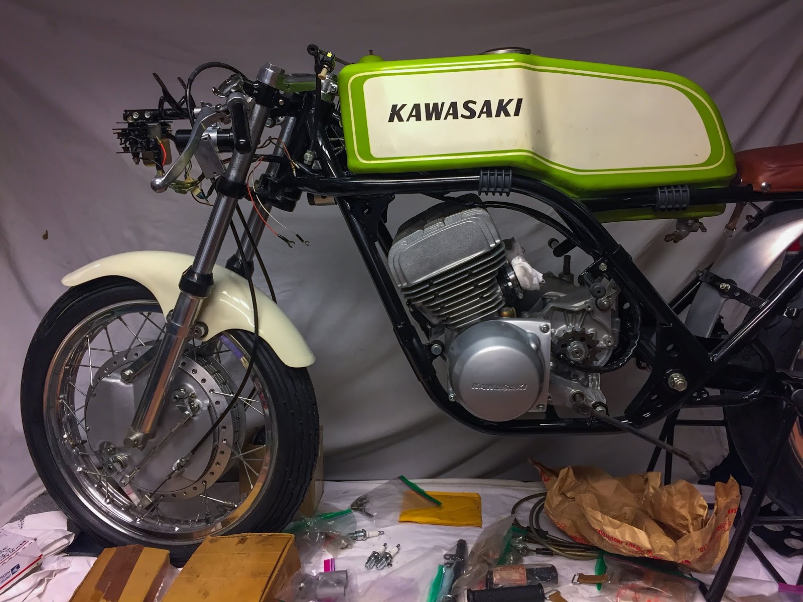
Let´s try to fit the tank... Worked fine! I do believe the wiring will have to go on the outside of the frame tubing. We´ll see about that later when it´s time to put it on permanently. For now I can enjoy this view of the bike with some more electrics on!
Time to move on to the drive chain. The problem with that was I had to get the clutch cable cleaned, lubricated and mounted on the clutch lever plus engine clutch release.
Here we go!
The H1R clutch cable has no adjuster midway between the engine and the handle bar as do the street bikes. I had a plan to replace my old, original one, with a very nice used street model clutch cable.
Two problems: it was too long and the adjuster would end up right where you can see it. Not good. A good clean and a pressure lube of the H1R cable had to do...
Here it is attached up at the clutch lever. I most often find it easier to fasten it at the lever first and then at the engine.
And here´s the reason why you need to connect the clutch cable before putting the chain on.... When the chain is on, it is almost impossible to reach the clutch release and adjusting it.
Here it is attached AND correctly adjusted. When the release lever is resting at the approx 8 o´clock position with only minimal free play you´ve got it correct. Imagine where the force you pull on the cable with will do the most good. Yeah, at 9 o´clock, at a 90-degree angle.
If more play develops during driving you adjust at the handle bar lever until you have to get back down here and readjust at the release. Rather ingenious actually!
The video below shows how the clutch works. very cool to be able to see the action on a motorcycle clutch in real life! These babies are most often hidden behind engine covers and run in oil and can never be seen.. Nice!
OK, the clutch is working. Drive chain up next. I bought a simple, non-O-ring, 530 DID chain. Of course it was way too long... It had to be cut to fit the bike. One would think, after all these years, I would have gotten myself a chain riveting/chain cutting tool. No, I did not. I do it the old fashioned way. First I need to measure how many links to remove. I find is easiest to measure on the rear sprocket. Be sure to have the wheel at its front-most position in the swing arm. Stretch the chain as hard as you can by hand and place the correct link next to the end link. be sure to get two "inner" links next to each other. If not, you´ll end up needing a "half link" to get the chain together. That is unnecessary in 95 % of the cases.
Once you have decided where to cut the chain, mark that very rivet carefully and then grind it off with a grinder or Dremel toool. Then use a small mandrel and hammer to get the rivet out. And there you go! Chain cut to size...
To the right you can see why it is important to cut the correct link. The chain lock goes in from behind and now the chain will stay in place all by itself.
When the link cover is in place you put the chain lock clip in place with the opening facing away from the chain´s drive direction. This clip can later be secured in a couple of ways. I´ll most certainly use safety wiring. Many do use silicone to keep it from rattling loose, but I believe wiring was more commonly used during the day.
Next up was getting the rear wheel permanently attached to the swing arm. I had to address the attachment of the rear brake cable at the wheel and rear brake pedal position adjustment screw.
To do this I had to get the bike off the stand and down on the floor. The rear brake pedal attaches to the right, rear foot rest and that had to come off to change the position of the screw.
To the right here, job is done!
I have the screw head below the bracket and the lock nut above. This way it worked out fine with the pedal at a good position adjustable up and down a bit.
At the rear wheel everything is done now. Rear brake cable attached and adjusted, rear wheel adjusted in the swing arm for correct chain tension and line-up with the engine sprocket. I found a perfect size split pin for the rear axle nut, please note it isn´t fully installed yet, I will most certainly remove the wheel at least two or three times more before this is done...
I also had to fix the bracket for the tachometer. Remember I had it refurbished a while ago with new rubber vulcanized to my original steel parts? It just had to be painted to go on the bike. Half an hour of masking and a rattle can spray of semi gloss wheel paint got that sorted. I have no problems using the slightly inferior spray colors from cans since the coats of paint on these bikes really are very thin and mostly without any primer at all. Well, here it is, drying over night.
I have many small things I need to fix all over the place. The bracket for the "chain cover" was one of them. I measured the tube where it goes and bought a few different ones from eBay. the original part?
36024-003.. Yeah, been looking for ages.... No Joy! Here´s the one that was closest in diameter. 92037-1115. Muffler Clamp from KLT 250. I got two and modified one of them to fit my purposes.
I had to make it a little smaller and change the direction of the bolt brackets a bit. The welded-on nut could remain, it looks the part! It was more or less perfect to just cut off the part with the bolt hole and then massage it back to the circular shape but with the correct diameter. Now it is also ready for paint.
And here´s the chain guard with the clamp ready to go on the bike, once the clamp has been painted gloss black. I will also need to drill the hole in the front end of the guard. That end also has to be angled a bit... preferably before drilling. Those are all small, easy tasks that needs no bigger thought to be completed. Just some nice fettling in the garage.
That sums it all up for today! Work is ongoing now and progress is being made slowly but safely. It helps having 8 days off work here over Christmas and New Year... By the way, If I didn´t say it before:
HAPPY HOLIDAYS AND A HAPPY NEW YEAR TO YOU ALL!!
In 2019 this 1970 Kawasaki H1R will hopefully be done and up and running. Keep you fingers crossed!
/Per
I am sorry for leaving the blog for such a long time. It was never my intention it would be more than 7 months between posts in it, but that´s the way it ended up... My lack of motivation in the project, my getting another H2 to work on (which proved to be a whole lot more fun to do....) and the extremely tough job finding correct parts for the H1R are the major root causes for this delay in the project.
Please remember I never did set up any schedule for the restoration, because I guessed it would be hard getting stuff and I figured I might loose concentration and face times of diminishing motivation from time to time. I do fully understand if you think I´m having luxury problems here, but they are very real. Wouldn´t every Kawasaki triple enthusiast just dream of taking over this project? Absolutely! But they wouldn´t like the endless, resultless search for those obscure, extremely-hard-to-find-bits needed to continue working on the bike.
Believe me, it is very frustrating to know people are holding on to stuff they have in stock as some kind of investment instead of sharing it with someone actually working on a bike.... Oh well, enough moaning. Here´s what I have been doing the last couple of weeks!
I figured I´d start off with something easy. I knew from day one I would need to get a replacement for 92072-008, Band Tool, that holds each side of the fairing in place, connected to the frame by the two small "cups" you can see in the picture top left. Those parts are, of course, impossible to find. I´ve been looking for 2 years now and have come to the conclusion I´ll never find the original one. So, what to use as a replacement?
I looked up some alternatives on eBay and bought a few candidates. It´ll show later on I made a mistake here, but it is a rather understandable one.... On the right here are 3 of them and below follow a presentation of the crafts they came from. I know it is a parenthesis, but I find it amusing.
In the picture on the left you can see the Kawasaki WSAA 1973-74. A very early "One passenger water craft" that uses 92072-502 as a fuel tank band. Will I be able to use it on the H1R? Maybe, maybe not!
Here on the right is the Kawasaki Jet Ski 550 SX that uses 92072-3766 as a Battery band. Maybe that´ll work better...?
And last, but certainly not least... is the Kawasaki Jet boat "Jet Mate" from 1989-1992. Far from an H1R, very far... But will the 92072-3726 "Band" work as a fairing retaining part? The answer soon to come!
The "cups", still uncleaned and unpolished here, are attached to the fairing with a large headed M6 screw and then goes over the rubbers on the frame brackets as shown here on the right. The hooks are for attaching the fairing rubber (band tool) and pull them inwards and in that way keep the fairing snugly in place. All good in theory...
OK, first out is the WSAA fuel tank band. Way too long as clearly seen here. Nice shape on the metal hooks, but no, they won´t do. Too bad since thay were the oldest parts in my collection of replacements. On to the next one!
Next up is 92072-3766, the Battery band from the 550SX. Much better! My plan here was to remove that asymmetrical metal plate on one of the ends for a better look. But, as you can see, it actually pulled a bit too hard on the cups without that bracket so I tested the last option first...
92072-3726 seems to be the best replacement so far. I straightened the brackets some and slightly enlarged the holes to accommodate the hooks on the cups. Yeah, this works!
So, here´s my solution to the fairing retaining problem so far. A "Band" from a rather ugly and not very glamorous Kawasaki Jet boat.... Will it work in the end?
We´ll see... after all this fettling I realized they used TWO rubber parts, one on each side that was actually just wound up around the frame brackets and then hooked up to the fairing cups. I just thought I´d share this rather odd hunt for replacement parts with you guys...
The next project within the project came about after I finally found that illusive 21103-004 cam. Suddenly, one day a few weeks ago, it turned up in my saved searches for H1R-parts on eBay. It was my dear friend and "parts pusher" Dave Howard in England that had posted one on eBay. I double checked the part number within seconds on my iPad, where I keep the parts catalogue, and bought it! I wrote him a "friendly" reminder of the list I sent him about two years ago where this was one of the parts I needed for the restoration. He was very sorry for his mistake, forgetting about my wish list, and offered me a second one right off the bat. They arrived safely after a few days. Thanks a lot, Dave. These are badly needed here!
Such small things and still so very, very important. I´ve been searching for these for more than 2 years and have seen exactly 0 during that time. And now I have 2 of them!
Not only did he list the cams, he also listed a set of NOS condensers for the H1R. Yeah, I know, I have a couple of sets already... But, as I said earlier, when something shows up... BUY!
Now it was time for a very interesting comparison. What is the difference between 21103-004 and 21103-005. Ignition cam for the H1R and the H1B? After a first quick glance there seems to be no difference at all. Note I had to label them very carefully not to interchange them.... From this angle there is no difference visible. There are some marks on the side of -004 that are not present on -005 but when it comes to measurements I couldn´t find anything different.
Let´s try another view. From the topside. Here i have tried to catch the difference in angle (if any) between the slot at the bottom where they attach to the rotor and the slot at the top where the timing mark plate is situated. I see none.
I also measured the diameter of the hardened surface where the breaker point tab is resting and opening for the timing cam on these babies. Same diameter both on top of the cam and at the lowest part. There seems to be no difference in angle for the highest point of the cam either. the only thing I´m having problems measuring is the "duration" of the breaker point lifting surface. Well, since they are different part numbers I guess there is some kind of difference between them but, so far, I haven´t been able to locate it...
Anyway, that research will continue. I have two -004:s, remember. And a couple of -005:s for the H1B. On the right here are the parts now ready to go on to the bike!
My refurbished stator (still with H1B condensers), the rotor, the cam (now the correct one), fasteners for the stator to the engine cases, timing plate and the long fastener for the rotor, cam and timing plate. Let´s start putting the ignition on...
Here we go! First of all the small 3mm woodruff key I managed to locate in my previous post and then the rotor. This is a brand new, original, correct part number, rotor for the H1R ignition. Nice!
The correct ignition timing CAM, 21103-004, now finally in place. Next is the stator itself and then the ignition timing plate and the retaining bolt that attaches the plate, cam and rotor to the turning part of the igniton/generator.
And here it is all in place! The three retaining screws attach the stator to the cases, the large bolt secures the turning stuff on to the crankshaft.
Imagine the rotor inside the stator. That rotor is one big magnet rotating (with the turning crankshaft) inside the stator (stands still...) that is lined on the inside with multiple windings, stator coils, that generate electrical power together with the turning magnet inside. This alternating current is then fed to the rectifier and voltage regulator up front on the bike. The points generate the sparks in the spark plugs through the ignition coils and the condensers take care of the surplus power each time the points open up for a new spark. As soon as I can locate the correct ignition coils I will also be able to replace the H1B condensers with the correct H1R ones. Any year now.....
The final touch for the day... That NOS H1B engine cover. Looks a bit too nice but it´ll have to do for now. I may change that later on and try to find a surface that is more suitable for a racer that has been used for 4-5 races.
I managed to locate three correct length pan head screws in my own stock of fasteners. Of course I only use old, refurbished, Kawasaki fasteners whenever possible. I am lucky to have been working on these old bikes for more than 20 years and have never thrown anything usable away, ever! I always try to reuse those old battered screws and restore them with renovated, or just cleaned, threads and straightened pan heads. A fresh coat of zink makes them look new again.
Here´s another one of those nice finds happening on eBay from time to time... NOS engine sprockets, specifically for the H1R. 15 teeth, one of the optional sizes available for different gearing. I think i paid 25 bucks each, which really is a steal!
I really enjoy the hobby when these beautiful parts show up and I´m able to get them. Look at those lightening holes around these sprockets! Not needed on the street bikes but on a racer? Sure! Every gram counts towards the final, total weight of the bike on the starting line. That, my friends, is what building these racers was all about during the early seventies. Racing and winning and putting Kawasaki up there as one of the contenders in the race to be the fastest bike on the track as well as on the streets....
Next up on my restoration is the electrical system and the other ignition parts on the bike. I will also need to continue with the rear wheel, the brakes and the drive chain. But before putting the chain on I need to clean the clutch cable and adjust the clutch pusher etc, etc... Well, I´m back at it. I´m thinking H1R-restoration again 50% of my awake time. The other 50% is getting more H2:s to work on when I´m done with this build.
Stay tuned and, again, Sorry for the delay!
/Per
I´m still having problems motivating myself to work on the bike. I sure do have enough to do on it. It´s not that. I have plenty of stuff to go through and fix. Most of those small projects within the project don´t even need new parts, just man hours. Well, at least last week saw some action in the garage! Not much, but some...
As you can see here I´m working only on the ignition part of the bike right now. I´m still trying to find all the small bits and pieces missing here and there. This is the only place I have to store the large fairing in a safe place. Lots of padding on the seat and tank and here it can rest safely.
The ignition is coming together slowly bit by bit. Here I have gathered the parts I have found so far. As I have mentioned before I decided to go the easier H1B-route for now, concerning the ignition. Lots of NOS stuff here... The three H1B ignition coils, for instance. Brand new and hopefully usable together with all the other H1B parts here.
Since I have been unable to locate the correct H1R ( 21103-004) points timing cam, I´m going H1B (21103-005) also here. One NOS on the left in the picture and one used in the middle. To the right is the correct timing cam plate. Used on both H1R and H1B.
I have also located a NOS early H1 ignition cover. I think the original on the H1R was left with its raw aluminium surface. This one is painted silver, the only difference. I can live with that. Easy to fix when you feel the need to. The rotor is also a common part (21007-016). I found a NOS one at a reasonable price on eBay a year ago. As I said, finding parts is the hard thing, here. When something shows up, BUY!
And the stator I worked on in my last post. I still like the look of it!
Here´s another gem. 21071-004, Regulator. Common part between the H1R and the H1B. Behind it is the used rectifier I have located so far. If a NOS one shows up I might buy it! This regulator is actually not only NOS (New Old Stock) but also NIB (New In Box)... You need to keep up with the lingo when you´re surfing the net for parts...
Not all purchases are a success, though. I ordered 5 of these Woodruff keys thinking they would be correct for the H1R. Not so. I had to go back to the parts lists and try to figure this one out. More about that later on!
Gathering stuff and searching for that illusive little part over the net and via contacts is fun, but hands-on-working is really what is the most interesting part of this hobby. I´ll soon be needing to start working on the fairing and the fasteners on it. These are the original ones from the bike plus a few extra from "Tullar´n", the guy that repaired Janne´s and my fairing sets. They are called "Dzus" fasteners and was actually invented in the thirties by an american engineer of Ukrainian descent , William Dzus.

I knew so little about these things I had to google it... Here´s the actual patent from 1934. Really cool to see the stuff seems to be exactly the same in 1970 as in 1934. The principle is simple. The fastener is locked in place by pushing the two surfaces you want to join together. The small "Dzus" screw is pushed in to "catch" the wire part and is then turned 90 degress to lock them together. The tension in the wire keeps the screw from turning loose even during high vibrations. These are most commonly used in aircraft applications but also here, in racing.

OK, back to my fasteners. I was planning on getting a batch of new ones (they are readily available in many sizes...) but figured I could try and clean them up a bit. The part about not over restoring, remember? These had been painted at some point and had a little surface rust here and there. I counted the holes in the fairings and came up with a need of totally 9 sets. The parts list says 11... I believe it has to do with the number of fasteners on the bottom fairing. Mine has only 3 per side and pictures from other bikes show they have 4. This is something I´ll have to look into more later on. I´m thinking someone, "Esso" or Björn, cut the fairing at the rear part to accommodate big feet. Remains to be seen!
Well, nothing to lose... Just get on with it.
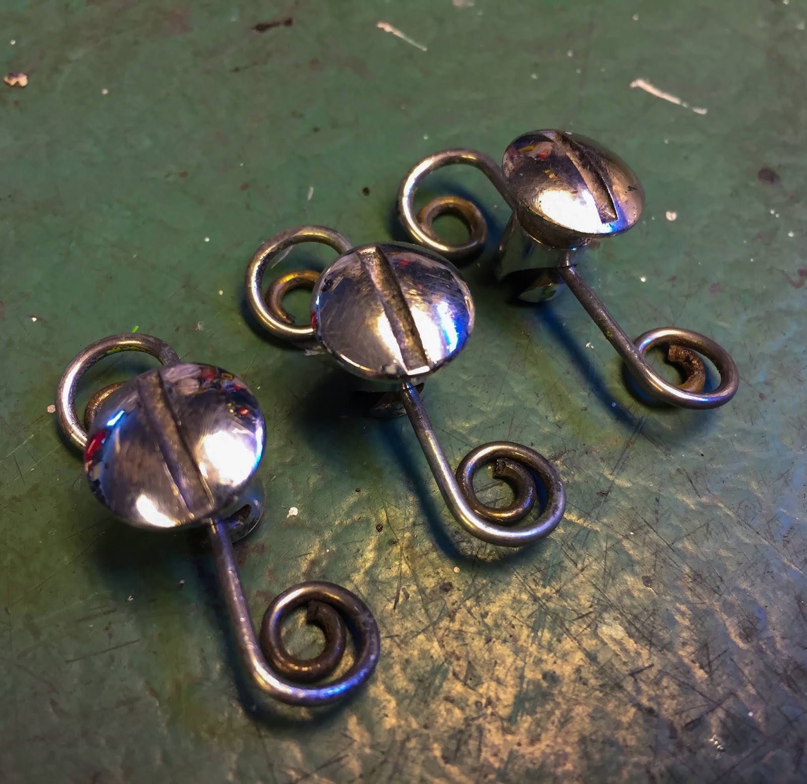
The first one done. That works for me! I prefer something with a bit of a story to tell compared to brand new stuff. This is not the last time I´ll use old, slightly tarnished parts instead of new ones.
During cleaning these, I came up with a plan to rezink them. That could have worked on the wire loops, but the actual Dzus screws are chrome. As good a clean as I could do would have to be enough.
It took a couple of hours... They are not in pristine, as new condition but they will fit my bike perfectly!
When "Esso" won the Swedish Grand Prix, July 1970, he had already raced it 4 times and Kjell Bogren entered the very first race in May 1970 at Falkenberg with it. That makes 5 races before the race I intend to duplicate its looks from. That gives me a lot of leeway when it comes to condition of things!
Sometimes it´s better to ask locally before buying things on a whim over the internet. I asked Ebbe about the Woodruff keys on H1 and H2:s.
"The H1:s and the H2:s both use 3x4,9x14 mm woodruff keyes in that location. I can send one to you, free of charge!"
Thanks, that´s the one to the right here. One less thing to worry about!
A couple of days later when I was rummaging through all my boxes and drawers searching for something else, I stumbled across these babies... Yeah, of course, the small 3mm woodruff key together with its larger 5mm cousin and a sprocket lock nut. These are some extra parts supplied, free of charge, by "Patrick Bras" of France when I ordered a larger quantity of H2 parts a while ago. See? I always do that! Ok, now I have at least two 3 mm keys and six 5mm ones. Not counting the ones I have, but haven´t located... yet. AAHHRRGG!!
So, here we are at present. The ignition is more or less complete and can go on the bike any year now...
Another H2 was mentioned in the headline of this post. Well, Someone made me an offer I couldn´t refuse. An H2A 1973 that has been sitting for 15-20 years. The last owner had the body repainted , bought new exhausts, wiring loom, decals etc, etc. I won´t write about it here, in this blog, but now you know why I´m distracted from working on the H1R instead. I told you I wouldn´t start on one of my other two H2:s... That´s sort of true since I got me another one!
The plan here is to put the engine back in the frame and mount as many parts as possible on to the bike to make it easier to store. When I bought it everything was in bits. During the first day of fettling with it I had the seat mounted, rear light and fastback with all its internal parts in place and cleaned up the fuel tank, sidecovers front fender and mounted that.... Today i fixed the front brake master cylinder that wasn´t working properly. Next is the engine.. We´ll see if I can stay away from putting on an exhaust system, clean the carbs and start it up... I´ll let you know!
Thanks for reading and keep driving safe out there.
/Per
 Now it was time to try and locate all parts needed. I had two regulators, one NOS and one very nice used. I chose the NOS one. Better safe than sorry when it comes to electric parts. Everything else in the picture to the left will be mounted on the "spear" up front where also the tachometer is mounted.
 The regulator and the rectifier mounted on the bracket that goes on to the "spear". Note how the regulator is rubber hinged, This is actually original also on the H1R. The rectifier is just screwed in place.
 The used rectifier turned out just fine after some cleaning. You can see the three diodes there, all in black, that turns alternating current in to direct current for the electrical system. The regulator keeps the voltage within limits not to overpower the electrical circuits. That one is a mechanical part that will not function properly when exposed to vibrations, hence the rubber mounting. There´s always a reason....
 Next was fixing the coils for mounting on the bike. The H1B uses a whole lot more stuff around the coils to keep them from vibrations and also weather. I don´t need any of it. They do have different part numbers in the catalogue but the actual coils are the same. The length of wiring and the different brackets make out the differences.
 I´ll probably not use the wiring on the coils but they can remain, the large rubber boots have to go, though. The same goes for the clamps. There´s no room under the steering head for that large double clamp. And that´s not the way it is supposed to look.
 To the right here is what´s going on the bike. Three H1B coils and the clamps from the Kröber coils plus that small, square, part that´ll work as a spacer for the two coils under the steering head. They have all been refurbished and rezinked. Sorry to say, even the correct H1R ignition coil clamps, 92037-052, are impossible to find... These will work fine, though.
 Three "Diamond" coils ready to be mounted to the racer. Note that the current feed lines are all brown and the others are color-coded to fit L,C and R cylinders on the H1B 1972.
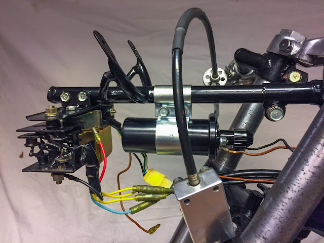 So far so good, The parts in place. The final fitment will probably be somewhat different so I´m not tightening the parts fully just yet. No safety wiring either since my experience tells me I´m going to change everything at least two or three times...
 Before putting these parts on I also had to straighten the "spear" a bit. I noticed it didn´t line up perfectly with the bike´s center line. Easy fix in my large vise. The rod is made from very thin-walled tubing and could easily be massaged straight. Without even ruining the paint. Thanks!
 Now for the wiring from the engine to the electrical "central" up front. I´m just trying to hook things up to get a feel for the length of the wiring and where to locate it when the time comes. Placement of the wiring is crucial on many bikes to be able to get room for all cables etc that need to pass close to the steering head. On Honda CBX:s there´s even a "wiring tracing diagram" to follow in order to get everything in place. No need for that here, though.
  Here I have managed to get the two front coils in place. I believe these two will be the left and right cylinder and the one up front will be the center one. That seems to make most sense here. Of course I had to move these further rear than I would like, but these coils might be a tad longer than the original ones and they ended up touching the frame tubes if not slided far to the rear in their clamps.
 Let´s try to fit the tank... Worked fine! I do believe the wiring will have to go on the outside of the frame tubing. We´ll see about that later when it´s time to put it on permanently. For now I can enjoy this view of the bike with some more electrics on!
 Time to move on to the drive chain. The problem with that was I had to get the clutch cable cleaned, lubricated and mounted on the clutch lever plus engine clutch release.
  And here´s the reason why you need to connect the clutch cable before putting the chain on.... When the chain is on, it is almost impossible to reach the clutch release and adjusting it.
  OK, the clutch is working. Drive chain up next. I bought a simple, non-O-ring, 530 DID chain. Of course it was way too long... It had to be cut to fit the bike. One would think, after all these years, I would have gotten myself a chain riveting/chain cutting tool. No, I did not. I do it the old fashioned way. First I need to measure how many links to remove. I find is easiest to measure on the rear sprocket. Be sure to have the wheel at its front-most position in the swing arm. Stretch the chain as hard as you can by hand and place the correct link next to the end link. be sure to get two "inner" links next to each other. If not, you´ll end up needing a "half link" to get the chain together. That is unnecessary in 95 % of the cases.
 Once you have decided where to cut the chain, mark that very rivet carefully and then grind it off with a grinder or Dremel toool. Then use a small mandrel and hammer to get the rivet out. And there you go! Chain cut to size...
 To the right you can see why it is important to cut the correct link. The chain lock goes in from behind and now the chain will stay in place all by itself.
 When the link cover is in place you put the chain lock clip in place with the opening facing away from the chain´s drive direction. This clip can later be secured in a couple of ways. I´ll most certainly use safety wiring. Many do use silicone to keep it from rattling loose, but I believe wiring was more commonly used during the day.
 Next up was getting the rear wheel permanently attached to the swing arm. I had to address the attachment of the rear brake cable at the wheel and rear brake pedal position adjustment screw.
  At the rear wheel everything is done now. Rear brake cable attached and adjusted, rear wheel adjusted in the swing arm for correct chain tension and line-up with the engine sprocket. I found a perfect size split pin for the rear axle nut, please note it isn´t fully installed yet, I will most certainly remove the wheel at least two or three times more before this is done...
 I also had to fix the bracket for the tachometer. Remember I had it refurbished a while ago with new rubber vulcanized to my original steel parts? It just had to be painted to go on the bike. Half an hour of masking and a rattle can spray of semi gloss wheel paint got that sorted. I have no problems using the slightly inferior spray colors from cans since the coats of paint on these bikes really are very thin and mostly without any primer at all. Well, here it is, drying over night.
 I have many small things I need to fix all over the place. The bracket for the "chain cover" was one of them. I measured the tube where it goes and bought a few different ones from eBay. the original part?
 I had to make it a little smaller and change the direction of the bolt brackets a bit. The welded-on nut could remain, it looks the part! It was more or less perfect to just cut off the part with the bolt hole and then massage it back to the circular shape but with the correct diameter. Now it is also ready for paint.
 And here´s the chain guard with the clamp ready to go on the bike, once the clamp has been painted gloss black. I will also need to drill the hole in the front end of the guard. That end also has to be angled a bit... preferably before drilling. Those are all small, easy tasks that needs no bigger thought to be completed. Just some nice fettling in the garage.


