A month passes quickly by during summer time. Vacation is, since long, over and I´m back to work. I have managed to do 6 return trips to the US and 1 simulator flight test since my last update here. It´s not that I´m complaining, but I need more time at home!
Anyway, the turning point is finally reached! I´ve started assembling the bike. Finally....

I usually start my bike assemblies with the swing arm and the swing arm bushings. It is always a good idea to locate everything you need before starting assembly work. Remember I bought those NOS swing arm sleeves from the UK? Well, here they are! Together with the slightly battered brass bushings. I´ll have to look closer on those....

You might be able to spot the damage I made when removing them from the swing arm during disassembly. That will have to be adressed.
It´s always a true pleasure unpacking these small bags of NOS candy parts. Especially when it says "H1R" on the bags!

And here they are on the rezinked swing arm pivot shaft. Ready to go into the bushings.... Took me about 3 hours of grinding, straightening, polishing and wet sanding to get the bushings to accept the sleeves AND to enter into the swing arm. These parts need to fit tight and snug but must not lock up too tight. The swing must be able to move freely but with no play at all. Time spent here is well worth the effort later, when you don´t have to take everything apart again. Better do it right the first time!

Test fitting of the parts into the swing arm. A light coating of oil and in they go.... And hopefully out as well! Easy does it. You don´t want to get the parts stuck in there and have to beat them out, damaging them again. The NOS sleeves were probably a tad bigger in diameter so it took a while to get it right. There´s no tube inside the swing arm as on the street bikes and no grease nipple either. The two sleeves meet in the middle and the shaft goes through both sleeves. Everything has to line up 100% to be correct. If not, the shaft will not go through with ease and the swing arm will not move freely.

After a long (nice...) evening in the garage I got it right and could finally grease the parts up and mount them inside the swing arm!

Here´s the final result. The steel sleeve protruding a little bit outside the brass bushing, ready to take the shaft and bolt to the frame where the sleeves will be in contact with each other and the frame on each side. The swing arm will move freely on the bushings between the sides of the frame. At least in theory!

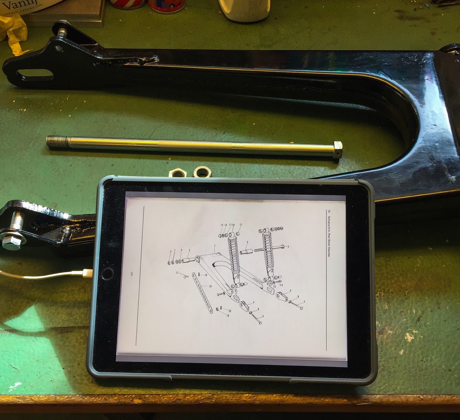
And here´s the shaft with its two nuts. They used two nuts to lock each other instead of one locking nut. Don´t ask me why... The parts list also calls for 2 washers on the same side as the nuts. That seems wrong to me so I´ll use one on each side instead. I thought the nuts were supposed to be the same, but it became obvious later on, that they are two different part numbers and the outer is much thinner.... I´ll show pictures later!

I have managed to convert all my scanned pages of the service manual/parts manual to one PDF, copied to iBooks on my iPad. Nice feature in the garage! Makes my decisions so much easier when I know right away when and how I divert from the manuals....

When I assemble a swing arm I always turn the frame upside down for convenience and ease. The wooden extra spare part box came in handy as a base for the frame to rest on.

Here we go! It is a real tight fit. The many coats of paint made the swing arm larger and the frame a little more narrow so the mating surfaces had to be sanded to bare metal (almost...) in order to fit the swing arm. A rubber mallet is a very useful tool when assembling stuff like this. You can strike as hard as you like and still not damage painted surface too bad... As you remember I don´t mind small marks of life on this bike. I want it to look genuine.

When the swing arm was in place, moving freely without any play, I couldn´t resist a quick mounting of the new KONI shocks from Robert Haag in the US. Boy, do they look the part! Absolutely fabulous! As I said before, we´ll see if these will be on there for good. I might have to go back to a used pair looking more like the Girling shocks "Esso" used. For now it looks and feels great!

Up next is the steering triple trees. Upper and lower, with the steering bearings. The steering bearing races all looked OK but I had one NOS and changed the one looking most worn. Probably totally unnecessary, but why not? Believe it or not, I had all of the 38 steering bearing steel balls left in the bag with the other parts! 19 in each bearing, top and bottom. You can also see the lower race already mounted to the lower triple tree in this picture. Easy tapping with a small hammer and a mandrel all the way around and around slowly drives the race down to the bottom of the tree.

The same goes for the races in the frame tube. Gently enter the race with the small hammer and then use the mandrel to slowly drive it down until it bottoms out against its seat in the tube. Tap only on the outer edge of the race and only very small and light blows. You can also use a socket that fits perfectly to drive down the race. The surface of the race is hardened and brittle and can easily be damaged! If it´s a too tight fit it helps to heat the frame tube with a torch or a heat gun. That will expand the tube and thus letting the race in easier.

OK, how do you know the bearing race is all the way down?
You can feel it when tapping on it. It sort of "bottoms out" and starts to feel more "solid" when tapping. To be sure I use an inspection mirror and turn it all the way around to check the race is in contact with the frame seat. This looks good!

Time to put the balls in place... This is one of the most tricky operations on assembly. I use lots of grease to hold them in place and carefully put all 19 of them into the race. Don´t loose them! They tend to vanish into thin air when dropped on the floor...
A good, thick, layer of grease on top of them secures them until the upper bearing race is mounted later.

This principle is also valid for the lower triple tree. Lots of grease to "glue" the balls to the lower race during mounting in to the frame tube. A coat of grease on the race in the lower part of the frame tube makes the greasing of the lower steering bearing complete as they come together.

There is no cover, no washer, no nothing between the steering stem lock nut and the top steering bearing race... Feels odd to me, but that´s the way it s supposed to be! I tightened the lock nut enough to take out any play but still loose enough to allow for free movement. The lock nut will later be locked in place by the top triple tree so no worries it will vibrate open....

Here we are! Swing arm in place, shocks in place, lower triple tree and steering bearing in place. Finally I have started the assembly of the racer... At last!
That is all for now... Next trip to the US is up tomorrow. C U in Chicago!
Nest time I´ll be working on the top triple tree, rear fender etc. Lots and lots of work to do but boy, isn´t that just wonderful.
Stay tuned for more!
/Per
Anyway, the turning point is finally reached! I´ve started assembling the bike. Finally....

I usually start my bike assemblies with the swing arm and the swing arm bushings. It is always a good idea to locate everything you need before starting assembly work. Remember I bought those NOS swing arm sleeves from the UK? Well, here they are! Together with the slightly battered brass bushings. I´ll have to look closer on those....

You might be able to spot the damage I made when removing them from the swing arm during disassembly. That will have to be adressed.
It´s always a true pleasure unpacking these small bags of NOS candy parts. Especially when it says "H1R" on the bags!

And here they are on the rezinked swing arm pivot shaft. Ready to go into the bushings.... Took me about 3 hours of grinding, straightening, polishing and wet sanding to get the bushings to accept the sleeves AND to enter into the swing arm. These parts need to fit tight and snug but must not lock up too tight. The swing must be able to move freely but with no play at all. Time spent here is well worth the effort later, when you don´t have to take everything apart again. Better do it right the first time!

Test fitting of the parts into the swing arm. A light coating of oil and in they go.... And hopefully out as well! Easy does it. You don´t want to get the parts stuck in there and have to beat them out, damaging them again. The NOS sleeves were probably a tad bigger in diameter so it took a while to get it right. There´s no tube inside the swing arm as on the street bikes and no grease nipple either. The two sleeves meet in the middle and the shaft goes through both sleeves. Everything has to line up 100% to be correct. If not, the shaft will not go through with ease and the swing arm will not move freely.

After a long (nice...) evening in the garage I got it right and could finally grease the parts up and mount them inside the swing arm!

Here´s the final result. The steel sleeve protruding a little bit outside the brass bushing, ready to take the shaft and bolt to the frame where the sleeves will be in contact with each other and the frame on each side. The swing arm will move freely on the bushings between the sides of the frame. At least in theory!

And here´s the shaft with its two nuts. They used two nuts to lock each other instead of one locking nut. Don´t ask me why... The parts list also calls for 2 washers on the same side as the nuts. That seems wrong to me so I´ll use one on each side instead. I thought the nuts were supposed to be the same, but it became obvious later on, that they are two different part numbers and the outer is much thinner.... I´ll show pictures later!
I have managed to convert all my scanned pages of the service manual/parts manual to one PDF, copied to iBooks on my iPad. Nice feature in the garage! Makes my decisions so much easier when I know right away when and how I divert from the manuals....

When I assemble a swing arm I always turn the frame upside down for convenience and ease. The wooden extra spare part box came in handy as a base for the frame to rest on.

Here we go! It is a real tight fit. The many coats of paint made the swing arm larger and the frame a little more narrow so the mating surfaces had to be sanded to bare metal (almost...) in order to fit the swing arm. A rubber mallet is a very useful tool when assembling stuff like this. You can strike as hard as you like and still not damage painted surface too bad... As you remember I don´t mind small marks of life on this bike. I want it to look genuine.

When the swing arm was in place, moving freely without any play, I couldn´t resist a quick mounting of the new KONI shocks from Robert Haag in the US. Boy, do they look the part! Absolutely fabulous! As I said before, we´ll see if these will be on there for good. I might have to go back to a used pair looking more like the Girling shocks "Esso" used. For now it looks and feels great!

Up next is the steering triple trees. Upper and lower, with the steering bearings. The steering bearing races all looked OK but I had one NOS and changed the one looking most worn. Probably totally unnecessary, but why not? Believe it or not, I had all of the 38 steering bearing steel balls left in the bag with the other parts! 19 in each bearing, top and bottom. You can also see the lower race already mounted to the lower triple tree in this picture. Easy tapping with a small hammer and a mandrel all the way around and around slowly drives the race down to the bottom of the tree.

The same goes for the races in the frame tube. Gently enter the race with the small hammer and then use the mandrel to slowly drive it down until it bottoms out against its seat in the tube. Tap only on the outer edge of the race and only very small and light blows. You can also use a socket that fits perfectly to drive down the race. The surface of the race is hardened and brittle and can easily be damaged! If it´s a too tight fit it helps to heat the frame tube with a torch or a heat gun. That will expand the tube and thus letting the race in easier.

OK, how do you know the bearing race is all the way down?
You can feel it when tapping on it. It sort of "bottoms out" and starts to feel more "solid" when tapping. To be sure I use an inspection mirror and turn it all the way around to check the race is in contact with the frame seat. This looks good!

Time to put the balls in place... This is one of the most tricky operations on assembly. I use lots of grease to hold them in place and carefully put all 19 of them into the race. Don´t loose them! They tend to vanish into thin air when dropped on the floor...
A good, thick, layer of grease on top of them secures them until the upper bearing race is mounted later.

This principle is also valid for the lower triple tree. Lots of grease to "glue" the balls to the lower race during mounting in to the frame tube. A coat of grease on the race in the lower part of the frame tube makes the greasing of the lower steering bearing complete as they come together.

There is no cover, no washer, no nothing between the steering stem lock nut and the top steering bearing race... Feels odd to me, but that´s the way it s supposed to be! I tightened the lock nut enough to take out any play but still loose enough to allow for free movement. The lock nut will later be locked in place by the top triple tree so no worries it will vibrate open....

Here we are! Swing arm in place, shocks in place, lower triple tree and steering bearing in place. Finally I have started the assembly of the racer... At last!
That is all for now... Next trip to the US is up tomorrow. C U in Chicago!
Nest time I´ll be working on the top triple tree, rear fender etc. Lots and lots of work to do but boy, isn´t that just wonderful.
Stay tuned for more!
/Per
Inga kommentarer:
Skicka en kommentar