The rear wheel and those seat covers have been sitting on my garage bench looking at me the last couple of weeks. Finally, the last few days I found the time to get down there and talk to them. During work and a few days preparing for the final efforts in the last bathroom I´ve been thinking about what size of drive chain to choose. 530 (stock) or 520, smaller and better-looking, in my opinion. The decision was finally made...
I´m going stock, 530. No matter what, I´m trying to recreate the look the bike had when "Esso" won the Swedish GP 1970. That means 530. I´m quite sure he didn´t alter the chain until much later, if he ever did at all.
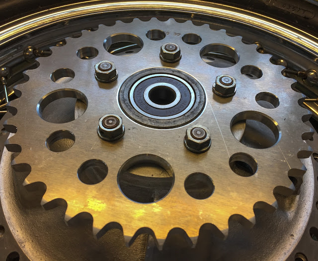 So, I opted for the 530 sprocket and had it mounted to the rear wheel. Of course I had managed to loose one of the nuts. I found a batch of NOS ones on eBay and got them home. Any day now I will find the lost one, I usually do...
 I´ve been looking on a few YouTube videos on how to safewire bolts and nuts. It seems to be a complicated task if your application demands high security like on aircraft parts, propellers etc. Here it is not so important. The objective is to keep the nuts from turning loose during driving on a racetrack. I can do that.....
 I found a few different patterns to use depending on how many nuts you need to secure. I decided to go with the "Two-nut" method and extend it to my 5 nuts. The idea is to create a wiring that is tensed in the correct direction to hold the nuts in place in relation to each other. The start is made with enough wire to go around the 5 nuts and positioned halfway through the first nut.
 I´m slowly working my way around the nuts trying to get the wire as tight as possible between them. The "How-to-videos" often describe how you should put the wire around every nut, but I found that unnecessary on the ones between the first and last. Right or wrong? I don´t know. As long as the nuts can´t move I´m happy. The tool is a simple safety wiring tool called "Wapid Wiring tool" Cheap, not so good, but it does what it´s supposed to...
 Here on the left, you can see the "correct" way to route the wire on the nut to the left in the picture. Next I would take the lower piece of wire and go round the nut, the higher goes through the hole in the nut and joins the lower on the other side. Then I would continue turning them towards the next nut.
 Here´s what I did instead. In my world this secures the nut just as good. Looks better to me, so that´s the way it was done on the last nuts.
 And Voila´, here´s the finished result. I know it´s not perfect in any way but it´s my first try at it. The next time I´ll be better and know slightly more on how to do it. I believe the last strain of wiring between the last and back to the first nut, for instance, is unnecessary. They are both locked to the second and fourth nut respectively. But it looks better with a complete circle, though.
 The next task was getting the rear wheel back on the bike. Last time I did this it went surprisingly smooth... Not so this time! I´m off to a good start here with the rear axle, chain tensioner and the spacer in place for the wheel to be lifted up. So far so good!
 Got the other spacer, the brake plate and the right hand chain tensioner in place and the axle went through just fine. Wheel turned, no hick-ups... Until I checked the clearance between the sprocket bolts and the swing arm/chain tensioner. Now, That´s Close!
 And here´s the answer. They have been in contact. I vaguely remember thinking these tensioners didn´t look like they do in many eBay listings or in my parts manual. There they are smooth, no pressings on the side like these have. Why didn´t I have trouble with this the last time?
 And the answer is here! One of them has been altered... By simply hammering that pressing out to make it smooth. You can see that tensioner here on the left. I had merely put them on the "wrong" way around. OK, someone argues... Get NOS ones! Yeah, I might do that, but for now these will have to do. AND, they were on the bike, they will do their job, so I might just keep´em!
 And here´s the one going on the right hand side of the bike where there´s no sprocket bolts to interfere with the tensioner. Notice how there´s a built-in washer with an index on the outside of the tensioner? That´s to be able to adjust the wheel straight in the swing arm to correctly line up the two sprockets.
 The next project was to drill some used, but very nice M10 X 1,25 engine mounting bolt nuts from a street H1-69 I had in stock. the nuts used on the racer were in as bad nick as the long bolts. Not good enough. This is another thing I had never tried before. Drilling with such a small drill bit (1,5 mm) is a delicate thing. First I tried a 2 mm one. I broke it off at the first try. Hmm, better be more gentle. The hard part here is starting the hole at a 90 degree angle and then gradually, without braking that friggin´delicate drill bit, changing the angle so it drills the hole from one flat surface to the other and not straight through to the threads.
 Something like this! A nice hole to secure the nut with. Notice these M10 nuts are quite small in socket or key size. Not much material to drill in. I think they will be perfect for the racer even though they came from a street bike. On the H2:s there are special "locking nuts" used to fit the engine to the frame. I could have used some of those, but I don´t think they were used until 1972 so they would be wrong here...
 It took a while, but here they are. 3 for the larger bolts under and on the front of the engine and two for the upper, rear mount. As you can see I didn´t get them to look exactly the same. Each drilling was a happening, to say the least!
 No washers on the bolt head side. Strange, but that´s the way it is supposed to be. One lock washer per nut on the other side. Of course I had forgotten one of the rear bolts is an M8... Also a difference from the street bikes where both bolts are M10. Ergo, I had the pleasure of drilling an M8 nut as well!
 I can´t help thinking it´s funny the way they use rubber washers as some kind of vibration damping method...
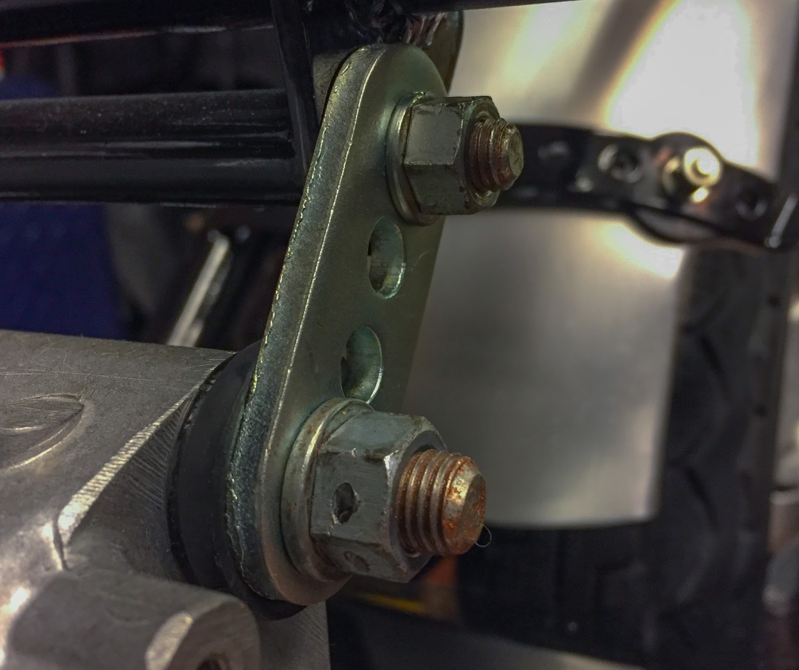
If it works? I don´t know. The engine for sure isn´t "rubber-mounted", it just has some rubber washers between the steel parts. Strange. Well, as I was tightening these two I had to plan for the safety wiring. You want the securing to be effective and the way to accomplish that is this....
 The twisted part of the safety wire is routed at an angle that secures both nuts to each other. Imagine the lower one loosening. That means the wiring is tightening the top nut harder and vice versa. I know it could have been more tense, but I´m getting there! This is a form of art. Takes time to master it, but I will get better. I Have to! The rest of the engine bolts and their safety wiring had to wait until I got back from work.
As I did that a couple of days ago I had been in contact with Janne and he asked how my seat was progressing. He had tried to fasten the push buttons with tools of his own and made a mess of the entire project. I just had to try it... With the right tool!
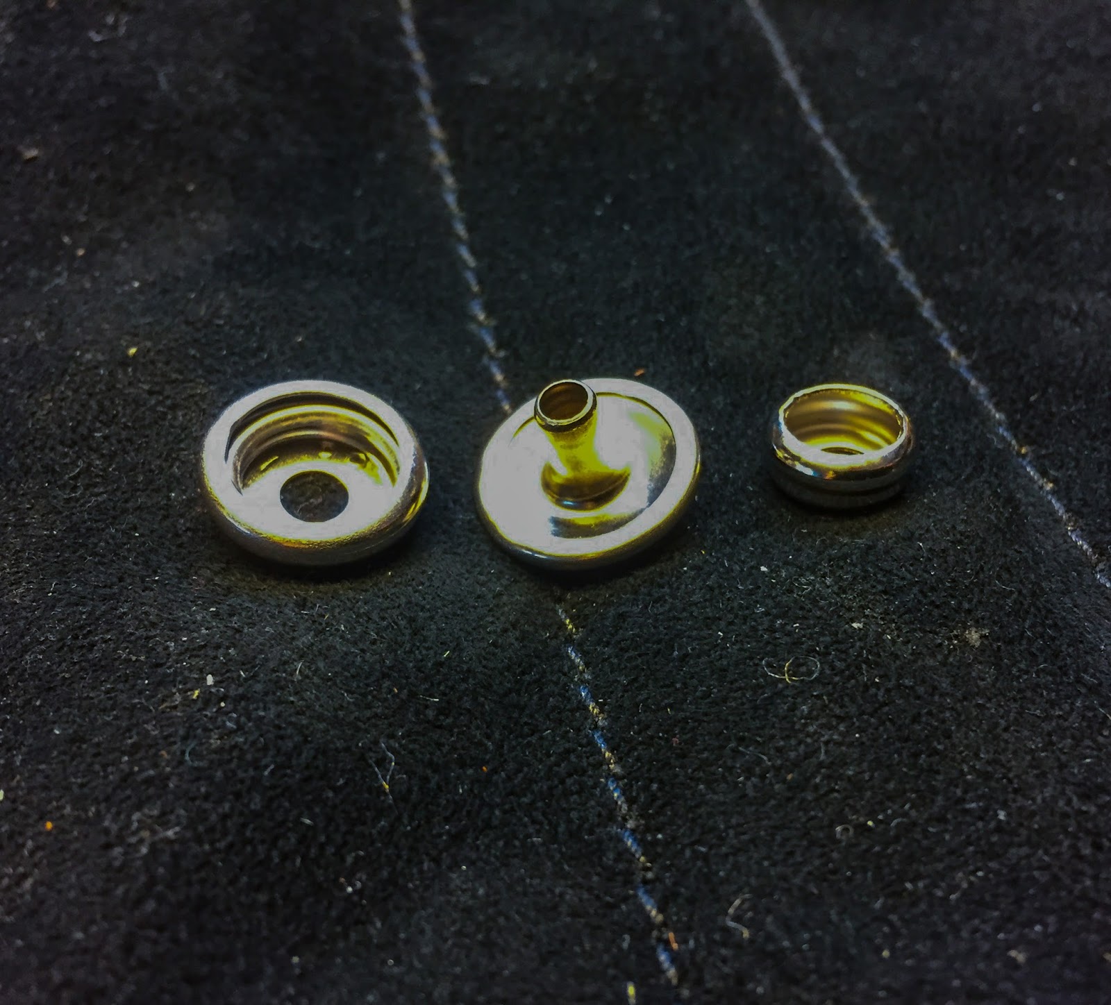
 Here´s the deal... The two parts on the left is riveted together through the cover material and the one on the right is riveted or screwed in to the fiberglass seat. Easy? Yeah, in theory.
 Here´s the key to success. The special "riveting, push button tool" It can be rented per hour or day from most boating supply stores that sell canopies etc. The place where I bought my push buttons had it...
 First you need to figure out what pressing socket to use in the tool. Here I have them lined-up to try and understand which one to use. Of course I had it all wrong, as you might notice. So my first press was an utter failure. The pieces fell apart at once. I had chosen the wrong socket...
 Before starting to press the buttons together I tried to plan how to do it best. The easiest push buttons to place absolutely correct was the two up front. They are close to the edge and the cover can really sit only in one way around the front edge. A good starting point!
 OK, got them measured up and the holes made. The tool is a "press-once-and-you´re-done" kind of machine that makes it easy to do an expert job! If you get the buttons in the right spot, you can´t really go wrong. Super sturdy and high quality tool. Being a tool fetishist I wouldn´t mind owning one of these at all.
 Here, on the underside, you can see how the tool "rolls" the edge of the top part of the push button towards the bottom part and makes a strong "rivet". Super nice!
 The front part of the cover fits nicely. I thought I would have to make the round "cutouts" a bit larger but that may not be necessary. We´ll see later on. Pär made the covers so that it is possible to adjust these without destroying any seems. Nice thinking and superb craftsmanship!
 I usually try to fasten any seat cover I work on front and rear first and then work my way around the edges stretching the cover evenly on each side. Now I needed to figure out the center point of the top rear part of the cover and have it placed in a way that would allow removing the rubber lid over the oil tank hole. Thankfully the cover has seems that tell exactly where the middle part of the cover is. Easy to hold it in place and mark the holes for the rivets with a ball point pen.
 "No guts, No Glory" Here we go! Now that the cover is on at the front and rear it is easy to work your way around the edges, one button at a time, symmetrically, constantly checking for everything to be straight and level.
 Each hole was made with with my leather hole punch tool. It has a number of different diameters and I tried to use as small holes as possible. You want the buttons to rivet tightly in to the material. I believe I used a 3 mm punch for the 4 mm rivets...
 To the left is the first try out of the cover. This time without any upholstery. It fits tight, but I think it´ll be perfect when it has been on there for a while and also filled with the rubber foam.
 The result of an hours work! I´m very pleased. The rent for the tool was negligible and extremely well spent money.
 From another angle. The rubber cap is easily removed and the way the buttons cross the seem around the cover is exactly the same as on the original one. The cover is made to fit tight so every mm was needed to get it on at all.
 This is the cover I´ll be using on the bike if/when I´ll ever try it. The original one will be used on display. Pär recommended I would treat the leather with a dubbin, a moisturizer for leather ware. I had a few brands to choose from but he actually said that ordinary Vaseline would be good enough.
 It got a couple of shades darker and more maroon in color when treated. I like it a lot! I´m super happy with the seat so far. I´ll repeat the treatment with Vaseline the coming weeks and also get the seat permanently fastened to the bike.
 I know the color of the seat covers were black back in the day, but I need to find some personal things to make the bike mine as well. This was an easy way to go about it.
 Now it´s time to check the ride height and adjust the rubber cushions under the seat. Here in this picture I have none of them in place. I think it looks real good this way. Maybe I´ll go for half of the rubbers. We´ll see...
 So, this is what it looks like right now in the garage. It is coming together nicely. Next is the permanent fastening of the seat and to try and manufacture a clamp for the (really small and stupid) chain cover on these bikes. Janne had two of those covers made, one for him and one for me... But I also need the clamp, 36024-003, if anyone has one laying around?!
That´s all for now... I´ll be back when some progress worth writing about has been done on the bike. Until then:
Stay warm and get those bikes ready for spring!
/Per
I´m going stock, 530. No matter what, I´m trying to recreate the look the bike had when "Esso" won the Swedish GP 1970. That means 530. I´m quite sure he didn´t alter the chain until much later, if he ever did at all.


If it works? I don´t know. The engine for sure isn´t "rubber-mounted", it just has some rubber washers between the steel parts. Strange. Well, as I was tightening these two I had to plan for the safety wiring. You want the securing to be effective and the way to accomplish that is this....

As I did that a couple of days ago I had been in contact with Janne and he asked how my seat was progressing. He had tried to fasten the push buttons with tools of his own and made a mess of the entire project. I just had to try it... With the right tool!


That´s all for now... I´ll be back when some progress worth writing about has been done on the bike. Until then:
Stay warm and get those bikes ready for spring!
/Per
Inga kommentarer:
Skicka en kommentar