Getting that restored exhaust system back on the bike sure felt good. It also gave me a boost to continue with the other stuff needing attention. I have had the cables (throttle and choke) laying beneath the bike on the lift ready for mounting for a while and now was the time to get it done.
Once the cables are on and working I will be also be able to get the grips on and, sort of, get the "cockpit" more or less ready for starting up.
Putting cables on also means adjusting their function and making sure everything works as it was once intended. Let´s start with the choke cable.
 I had stored the choke cable complete with the plungers and springs on at the lower ends
The first thing to worry about was the routing of the cable. Part in relation to the frame parts and part in relation to other cables on the bike or cables coming on later.
Once that was figured out it was more a matter of fettling in cramped spaces getting the plunger housings correctly aligned and screwed in to the carbs.
 When all three were in place in their respective carb body I greased the choke lever and its housing up at the handle bar.
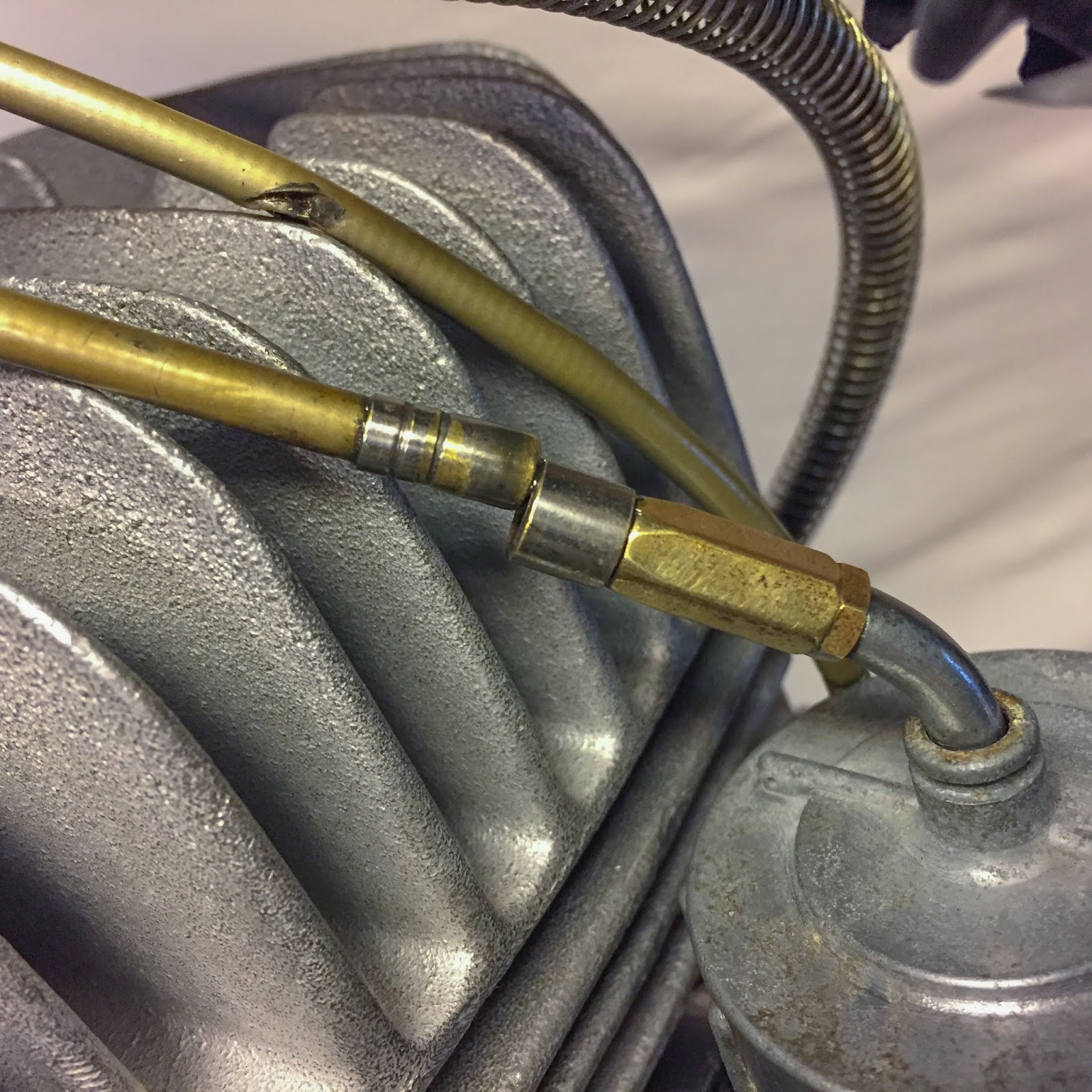
On the right here the parts are ready to smack back together. The cable is fitted to the moving part and the sheath is in position at the housing, top of the picture.
 On the left is a still leben picture of the tool tray while working with the cables...
It feels like a miracle every time I think about what I´m doing here and what I´m actually working on.
I think "surreal"is the best word that comes to mind.
 Now that the cables were fixed at both ends it was time to adjust it for proper functionality.
The choke plungers enrich the mixture of gas given to the engine when lifted from the bottom of their position in their seats. The more you lift the plungers, the richer the mixture. That´s the reason why they should lift quite simultaneously when pulling the lever.
 The easiest way to to that is to adjust the adjusters so the lift of each choke plunger is approximately the same when the lever is pulled.
Here´s one way to start. Screw the adjusters out a similar amount and measure the approximate length screwed out to be equal, or close to, on all three adjusters. That is a good starting point.
The fine tuning is done by measuring the exact free play on the cable by lifting the cable sheath from the adjusters. The chokes aren´t that sensitive, but if you are thorough here, you won´t have any issues with idling on a could engine later on.
 Normally there´s also an adjuster up at the lever where you can fine tune the tension of the cable for all three plungers at one point.
No such thing here on the racer. I guess they figured you would warm up the engine in the pit and then never use the choke during racing. That means there´s quite a large slack at the lever and I guess I´ll have to live with it or shorten the cable some.
Nah, won´t happen....
 One of the good moments...
Putting the left hand rubber grip back on the handle bar! The very same grip I carefully removed close to three years ago.
The left side is now done. Working clutch lever, choke lever and the grip in place. Nice.
 This is one of the best pictures so far, I think. You can see it is getting more and more complete.
 Ok, Lets move on to the throttle cable.
A little more issues here with the routing of the cable assembly. I tried a few different routings and ended up moving the tacho cable above the frame pipe for spacing of the throttle and choke cables.
I´m not sure it´ll stay there for good, but for now it gives me more space for the other cables. I checked the thickness of the cable versus the rubber blocks and it is OK. The blocks are thicker than the cable so it will not be pinched by the tank.
 When the routing had been decided (for the first time, there might be two or three more times, later on...) I double checked the position of the jet needles.
3rd position, the middle one, is a good starting point for later adjustments.
That small circlip keeps the needle in place in relation to the throttle slide and determines how much fuel is sucked up through the needle jet valve at part throttle opening. Intricate but ingenious!
 Here´s another smart solution. This small, strangely shaped, washer locks the throttle cable in place inside the throttle slide. You can see how it blocks the way out for the cable
The hole in the middle of the washer lets the jet needle protrude upwards. The little circlip in the last picture is located below the washer and thus holds the needle in place and at he correct height. Smart.
 The last part before putting the slide back into the carb is getting everything on to the throttle cable in the correct sequence.
First the carb body lid, then the carb body lid rubber gasket, the throttle spring and finally the slide assy with the needle in place. Tricky but fun!
 Now that the throttle cable was routed through the frame and connected to the throttle slides down at the carbs it was time to get the throttle grip ready and greased.
First a check in the parts manual that I have all the parts needed. No lock washers below the pan head screws. Interesting, but that´s the way its gonna be...
 Ball bearing grease, or normal universal grease, works fine. Take what you have handy. The throttle tube slides over the handle bar surface and a light coat of grease makes the action smoother and better. We want it to feel like new, right?
 These parts were easy to install. Plenty of slack at the cable end. Here on the left the throttle cable has been mounted in the lower part of the throttle grip housing.
 The throttle grip tube in place, greased and lubricated.
 On street bikes this can be a pain, but here the handle bars aren´t that wide so the throttle cable is long enough to allow the grip assy to be slid on to the handle bar without removing the cable again.
As I´ve said before, I usually do everything at least twice!
The next step was simple enough. Put the top part of the housing in place and tighten the screws. Check for cable clearance around the steering neck and also that the brake lever can move freely all the way in towards the throttle grip housing.
 All cables installed. The routing of the tacho cable above the frame tube might be changed later on, I have not decided yet. We´ll see when the tank arrives.
 On the left here I was checking the cable routing when turning the handle bar full right and left.
I might have to fasten the cables in a better way than just letting them sit loose and slide here and there.
The video below shows my simple technique using spoons to sync the carburetors. The left carb in the video (the right on the bike) seems to be reacting first when I pull the throttle grip. In this case you need to make sure all the cables are correctly seated and at the bottom of each adjuster...
 Here´s the problem clearly visible...
Too much slack in the cables can make the sheath hook outside the adjusters in an unwanted way. Come to think about it, that is why those small black rubber covers are there. They keep the cable in place inside the adjuster. Mine are a bit cracked and broken so either I will try to find new ones or I´ll just have to safe-tie them,
 If I pushed the splitter housing of the throttle cable a bit backwards I forced the cables in to the adjusters and the synchronizing is totally different. This is the way they are supposed to fit so this is where I started adjusting the cables. A large clamp held the splitter housing in place while I adjusted the carbs.
That sure looks a lot better, doesn´t it? The trick with the spoons works great and I use it all the time when working on street triples for the initial, static, sync of carbs. Later on when the engine is running it is a lot easier to use a vacuum instrument for fine tuning but, the thing is, most often I don´t have to change things at all from this basic adjustment.
Another difference on the race bike is the lack of an idle adjuster on the carbs... The street bikes all have some kind of idle adjustment possibility, either by a screw that lifts the throttle slides from the bottom of the carb bodies or a screw that lifts them from above, located in the carb lids, just beside the throttle cable adjusters. The H2:s have a screw on each carb body next to the fuel inlet and the H1:s use the adjusters from above. the function is more or less the same, just different ways to go about it.
It seems very obvious that idling is not the most important thing here. Once you get this beast started the rider is on the bike and can keep the engine running by simply keeping the slides lifted enough through the throttle grip. OR, you can adjust the slack of the cable short enough at the common adjuster up at the handle bar.
The short video above shows the action of the carbs so far. I believe this synchronization will be good enough for the first start of the engine.
I´m planning for a tour around the small Island I live on, here in Stockholm, after that first start up... We´ll see how the neighbours will react when "Esso´s" old bike rumbles through the streets. That will be something to remember! Not too far away in time, either...
 On the right here is a picture of the air intake of the middle carb. No air filter. You can also see the small black rubber protectors that will go back on the throttle cable adjusters later on. As I said, mine are not very good so I´ll try and find new ones.
 And there it was! The last of the exhaust retaining springs... I found it looking for electrical parts for the next project on the bike.
The Electrical system.
 I had a number of battery trays made a couple of years ago, remember? Now it was time to get one of them out and preparing it for the building of the electrical system. I had a couple of old, dry charged, batteries in stock and one of them was put in to service as a mock-up here.
If I remember correctly the most common type of H2 batteries look this way with the vent house on the left side together with the positive terminal and the negative one on the right. This is what I would prefer later on when I´m going to buy a new battery for the bike.
 The search for the electrical parts also revealed a couple of rubber parts I had missed/forgot about.
On the left here is the gear change rubber in place on the gear lever.
Fits like a charm!
 And here is the brake lever rubber grip, complete with the 6x12mm pan head screw that holds it in place. It is coming together now...
 I found two very good looking ground wires in one of the boxes and figured I could use them as a start on the wiring.
I´ve seen in numerous pictures from the racing pits that the engine also was grounded to the frame and battery terminal. Good ground is a vital part of any electrical wiring. I made it easy for myself and routed one from the engine to the battery terminal and one from the engine to the frame, at the muffler bracket to be exact. That´ll do for starters..
 There´s only one, small fuse in the electric wiring on the bike and it sits right at the battery plus terminal. this is a NOS unit from eBay. The exact correct part number. Worth its weight in gold...
I didn´t like putting another connector between the fuse and the battery terminal so I cut off the connector on the longest piece of cable going out from the fuse box.
 A cheap aftermarket connector was stripped of its ugly, blue insulation, and fitted to the wire with a piece of shrink tubing behind it.
If you use the correct tool, there´s no need to solder these connectors. They clamp extremely hard when used correctly.
This will look exactly like an original connector when I´m done with it.
 The final touch was made by the heat gun. The heat shrinks the tubing and makes a weather resistant, good looking insulation of the connector. Like it was built that way in the first place!
 This is the first trial fitment of the battery to the frame. Remember I had none of these parts and thus NO idea what it would look like or how it would attach to the frame. Simple enough. The battery tray hangs in the rubber bands that go over the frame tube! If you look closely underneath the battery you can see a small spring there...
 In the parts book that part number is the same as the springs that holds the exhaust pipes to the cylinders. Now, I only had six of them... But I found my stash of rear brake light switch springs, H2.
Would I be able to use one of these?
 The nice thing with these spring are the length of the lower par of the spring. That part could be extended and made to fit this purpose perfectly.
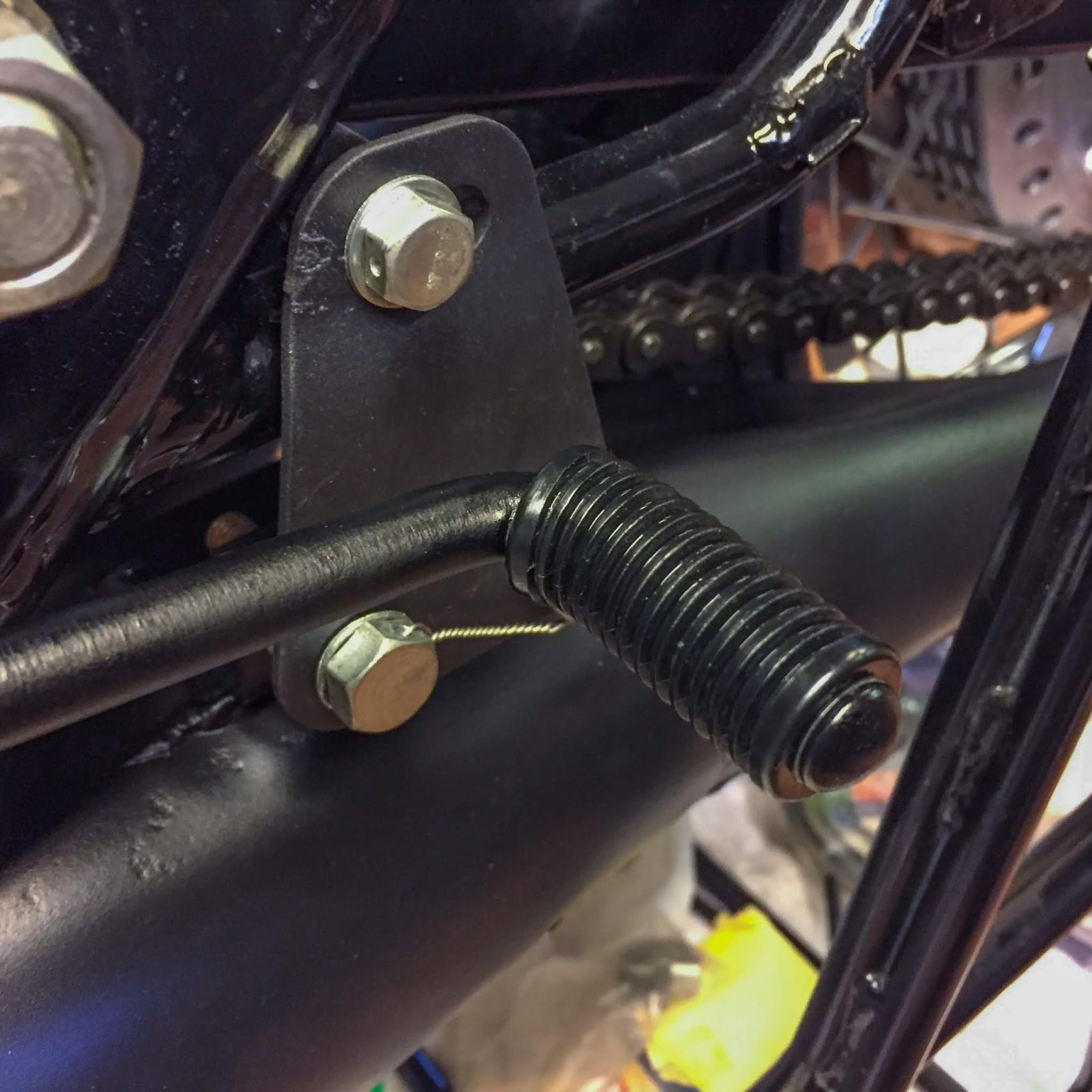
On the right here is what it looks like from the other side, through the frame. That works for me! It is even a Kawasaki part. Couldn´t be better. Later on I´ll just clamp it better to the battery tray. The long part of the spring is just perfect for holding it to the frame at that large hole. Another small victory.
 The top view of the battery tray hanging on the frame tubes. It´s quite clear they didn´t know how to solve this problem with the battery when they designed the electrical system.
Maybe they had plans for the CDI ignition introduced on the H1R-A the coming year but changed their minds ending up with a battery that needed mounting to the bike. Who knows?
The H1R-A 1971 doesn´t have any battery....
 Another one of my major concerns done! I really like that battery tray and all the parts around it. Turned out great.
 My next session in the garage will be wiring and ignition. On the left here is a great starting point for that work.
The battery box with the rubber bands holding it to the frame, the NOS fuse box with a nice, standard bullet connector for starting the wiring and that ground wire connecting the battery to the frame and the engine. I´m pleased so far.
 On the right here you can see the two ground wires from the frame to the engine and further on to the battery.
You can also see how tight the fit is for the battery tray in the frame. Not much clearance between the rear fender locking nuts and the frame tube on the right. Tight, but not touching!
 The last picture in this post. the status of the bike right now.
Carbs and throttle cable in place and synchronized, choke cable mounted and adjusted, the battery hanging solution figured out and the electrical system and wiring started. A couple of days more in the garage and I´ll be ready to adjust timing, ignition and checking for those precious sparks...
I need to figure out how to turn the engine fast enough for those checks without owning a pit starter. That´s a problem I need to address as well. Does anyone out there have a good tip on who makes and sells them? I´ll need one soon!
Thanks for reading and see you all soon!
/Per
Once the cables are on and working I will be also be able to get the grips on and, sort of, get the "cockpit" more or less ready for starting up.
Putting cables on also means adjusting their function and making sure everything works as it was once intended. Let´s start with the choke cable.

The first thing to worry about was the routing of the cable. Part in relation to the frame parts and part in relation to other cables on the bike or cables coming on later.
Once that was figured out it was more a matter of fettling in cramped spaces getting the plunger housings correctly aligned and screwed in to the carbs.

On the right here the parts are ready to smack back together. The cable is fitted to the moving part and the sheath is in position at the housing, top of the picture.

It feels like a miracle every time I think about what I´m doing here and what I´m actually working on.
I think "surreal"is the best word that comes to mind.

The choke plungers enrich the mixture of gas given to the engine when lifted from the bottom of their position in their seats. The more you lift the plungers, the richer the mixture. That´s the reason why they should lift quite simultaneously when pulling the lever.

Here´s one way to start. Screw the adjusters out a similar amount and measure the approximate length screwed out to be equal, or close to, on all three adjusters. That is a good starting point.
The fine tuning is done by measuring the exact free play on the cable by lifting the cable sheath from the adjusters. The chokes aren´t that sensitive, but if you are thorough here, you won´t have any issues with idling on a could engine later on.

No such thing here on the racer. I guess they figured you would warm up the engine in the pit and then never use the choke during racing. That means there´s quite a large slack at the lever and I guess I´ll have to live with it or shorten the cable some.
Nah, won´t happen....

Putting the left hand rubber grip back on the handle bar! The very same grip I carefully removed close to three years ago.
The left side is now done. Working clutch lever, choke lever and the grip in place. Nice.


A little more issues here with the routing of the cable assembly. I tried a few different routings and ended up moving the tacho cable above the frame pipe for spacing of the throttle and choke cables.
I´m not sure it´ll stay there for good, but for now it gives me more space for the other cables. I checked the thickness of the cable versus the rubber blocks and it is OK. The blocks are thicker than the cable so it will not be pinched by the tank.

3rd position, the middle one, is a good starting point for later adjustments.
That small circlip keeps the needle in place in relation to the throttle slide and determines how much fuel is sucked up through the needle jet valve at part throttle opening. Intricate but ingenious!

The hole in the middle of the washer lets the jet needle protrude upwards. The little circlip in the last picture is located below the washer and thus holds the needle in place and at he correct height. Smart.

First the carb body lid, then the carb body lid rubber gasket, the throttle spring and finally the slide assy with the needle in place. Tricky but fun!

First a check in the parts manual that I have all the parts needed. No lock washers below the pan head screws. Interesting, but that´s the way its gonna be...


As I´ve said before, I usually do everything at least twice!
The next step was simple enough. Put the top part of the housing in place and tighten the screws. Check for cable clearance around the steering neck and also that the brake lever can move freely all the way in towards the throttle grip housing.


I might have to fasten the cables in a better way than just letting them sit loose and slide here and there.
The video below shows my simple technique using spoons to sync the carburetors. The left carb in the video (the right on the bike) seems to be reacting first when I pull the throttle grip. In this case you need to make sure all the cables are correctly seated and at the bottom of each adjuster...
Too much slack in the cables can make the sheath hook outside the adjusters in an unwanted way. Come to think about it, that is why those small black rubber covers are there. They keep the cable in place inside the adjuster. Mine are a bit cracked and broken so either I will try to find new ones or I´ll just have to safe-tie them,

That sure looks a lot better, doesn´t it? The trick with the spoons works great and I use it all the time when working on street triples for the initial, static, sync of carbs. Later on when the engine is running it is a lot easier to use a vacuum instrument for fine tuning but, the thing is, most often I don´t have to change things at all from this basic adjustment.
Another difference on the race bike is the lack of an idle adjuster on the carbs... The street bikes all have some kind of idle adjustment possibility, either by a screw that lifts the throttle slides from the bottom of the carb bodies or a screw that lifts them from above, located in the carb lids, just beside the throttle cable adjusters. The H2:s have a screw on each carb body next to the fuel inlet and the H1:s use the adjusters from above. the function is more or less the same, just different ways to go about it.
It seems very obvious that idling is not the most important thing here. Once you get this beast started the rider is on the bike and can keep the engine running by simply keeping the slides lifted enough through the throttle grip. OR, you can adjust the slack of the cable short enough at the common adjuster up at the handle bar.
The short video above shows the action of the carbs so far. I believe this synchronization will be good enough for the first start of the engine.
I´m planning for a tour around the small Island I live on, here in Stockholm, after that first start up... We´ll see how the neighbours will react when "Esso´s" old bike rumbles through the streets. That will be something to remember! Not too far away in time, either...


The Electrical system.

If I remember correctly the most common type of H2 batteries look this way with the vent house on the left side together with the positive terminal and the negative one on the right. This is what I would prefer later on when I´m going to buy a new battery for the bike.
On the left here is the gear change rubber in place on the gear lever.
Fits like a charm!


I´ve seen in numerous pictures from the racing pits that the engine also was grounded to the frame and battery terminal. Good ground is a vital part of any electrical wiring. I made it easy for myself and routed one from the engine to the battery terminal and one from the engine to the frame, at the muffler bracket to be exact. That´ll do for starters..

I didn´t like putting another connector between the fuse and the battery terminal so I cut off the connector on the longest piece of cable going out from the fuse box.

If you use the correct tool, there´s no need to solder these connectors. They clamp extremely hard when used correctly.
This will look exactly like an original connector when I´m done with it.


Would I be able to use one of these?

On the right here is what it looks like from the other side, through the frame. That works for me! It is even a Kawasaki part. Couldn´t be better. Later on I´ll just clamp it better to the battery tray. The long part of the spring is just perfect for holding it to the frame at that large hole. Another small victory.

Maybe they had plans for the CDI ignition introduced on the H1R-A the coming year but changed their minds ending up with a battery that needed mounting to the bike. Who knows?
The H1R-A 1971 doesn´t have any battery....


The battery box with the rubber bands holding it to the frame, the NOS fuse box with a nice, standard bullet connector for starting the wiring and that ground wire connecting the battery to the frame and the engine. I´m pleased so far.

You can also see how tight the fit is for the battery tray in the frame. Not much clearance between the rear fender locking nuts and the frame tube on the right. Tight, but not touching!

Carbs and throttle cable in place and synchronized, choke cable mounted and adjusted, the battery hanging solution figured out and the electrical system and wiring started. A couple of days more in the garage and I´ll be ready to adjust timing, ignition and checking for those precious sparks...
I need to figure out how to turn the engine fast enough for those checks without owning a pit starter. That´s a problem I need to address as well. Does anyone out there have a good tip on who makes and sells them? I´ll need one soon!
Thanks for reading and see you all soon!
/Per
Inga kommentarer:
Skicka en kommentar