It´s on wheels!
I really got inspired getting the rear wheel finished, so I moved on with the front one. Getting the brake plates complete was the task of the day. I had all the parts out and sorted them, remember. Well, it showed later on I didn´t do that thoroughly enough. More about that later.
The front brakes differ a bit from the rear one. There are two cams, each moving one brake shoe on each side, 4LS technology, up front where there´s only one cam moving both shoes on the rear. That means two of everything on each side. Two cams and two shoe pivots. The pivots are fixed to the plate and only need a light coat of grease or copper paste for the shoes to move easily. The two cams can be greased from the outside and need more regular attention. I learned from the rear to mount these strong springs before putting the shoes on to the plate. With everything greased up and double checked the mounting was fairly straight forward.

As I started checking and assembling the outer brake levers I noticed a problem... All of them have steel thread inserts to reinforce the threads inside. I believe these might be factory mounted. all 5 levers, front and rear have them. The problem was one of them had broken and partially followed the screw out when I disassembled the parts. On the left here you can see the steel thread outside the lever. The easy fix would have been to choose a larger screw and just thread the hole. No can do! This needed attention.
Many years ago I bought the most common thread repair kits from Helicoil. Yes, I had the M6x1.0 in stock. Thank you, my hoarding obsession!
These are fantastic kits with everything you need to make a permanent thread repair included. This one has 9 mm length thread inserts, drill, tap mounting tool and the mandrel to finish the work. All in one convenient box.
Usually when you start a thread repair you need to drill out the hole a bit. The drill in the kit is the correct size for the threading tool, tap. Since there already were inserts in these parts I figured I would be OK just to clean the threads with the correct tap. Worked like a charm!
The next step is mounting the new insert into the hole. Here it is on the mounting tool ready to be "screwed" in to the thread. The idea is simple: replace the broken aluminium threads with a more sustainable one made of steel.
That´s why you have to make the hole larger and then smaller again inserting the new, much stronger, insert. Genious.
This part of the process is delicate but not difficult. the insert had to be screwed through the first part of the lever into the second one where it is supposed to go. No big deal, the mounting tool holds it firmly as long as you turn it the right way. Here I´m halfway through the first layer.
And here I´m through and in to the second. You need to get the end of the insert at least a couple of threads into the goods for it to stay properly. You can also use a drop of Thread locking glue, like Loctite, to secure it in place.
The last step of the process is removing the little "tab" used for the mounting tool to drive it in to the thread. This tab will hinder the screw from going through if not removed. The mandrel is used to simply tap it off.
And here is the confirmation the repair is complete! the small end tap out of the hole. You do not want this part around in the hole when you´re done. Here it is not that important, but imagine a repair on an internal engine thread....
Time to get the levers and adjusting rod on to the brake plate. Careful comparison with the pictures taken earlier got it right in the end (I think....). If I goofed here it´ll show when I try to adjust the brakes and mount the cables to the levers. And then I´ll just have to remove everything and do it all over again. That isn´t at all uncommon in my garage. Experience tells my I do everything at least two times....
The ventilator plates on the front drum also needed some TLC. This one is the worst of them. The net had separated from the frame and it had also been bent and damaged earlier. My plan to replace them with new ones didn´t work out that well so I had to fix them as good as possible.
It took a few ours during two days of wonderful garage work to get it done! Here it is, ready to be inserted in to the front wheel. The brake shoe pivots have been secured with cotter pins but I´ll wait until everything is finished and adjusted on the bike before safety wiring the screws on the levers. I do not want to do that twice as well...
The front brake finished. You can see the restored ventilators and also the surprisingly good brake shoes. They show almost no wear at all. I believe Björn got a couple of new sets when he bought the bike from Flöter. I´m lucky, because finding these shoes are difficult. There´s always a possibility to restore old ones and have new brake linings glued on to old shoes. I´m happy not to have
to deal with that as well!
Front view of the front brake. I´m very happy with the turnout of this part! When you have the drum loose like this it is also possible to figure out how to adjust the levers later on. I know from a previous restoration of a Suzuki GT750 J 1972 that these 4LS brakes actually are quite efficient when adjusted correctly. You need to be thorough and meticulous doing it, though. well, that adventure awaits in the future.
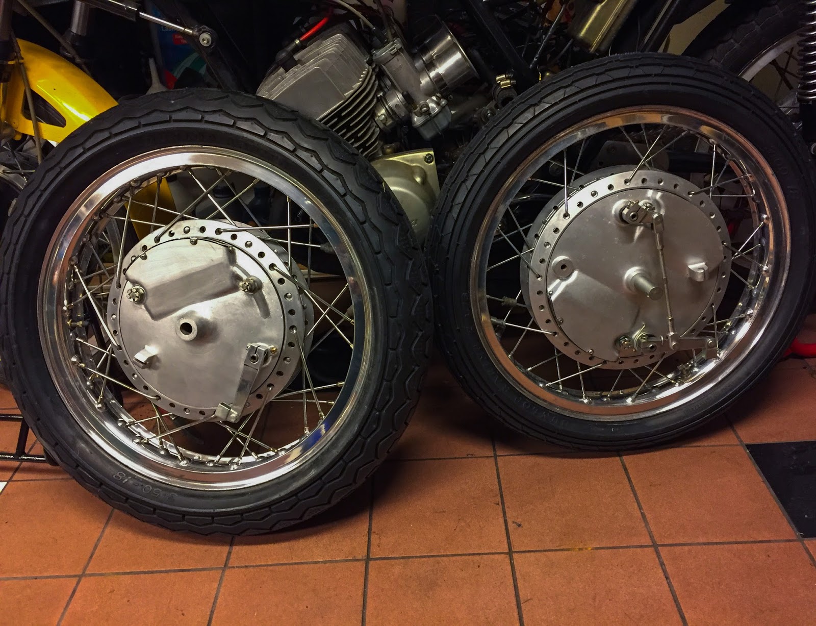
For now it was very rewarding to put the brake plates in to the wheel and snap a couple of pics. I´ve said it before... These are work of art!
The front and rear wheel ready to go on to the frame. Now I need to get going with the rest of the chassis. I need the main stand to mount the wheels and to get the main stand on I need the front foot pegs in place. To get them in place means I have to fix them first! Here we go!
The pegs were painted together with the frame and swing etc. All the other parts were rezinked and stored in bags. In this picture we can see the old foot peg rubbers and the refurbished pegs, springs and washers. I had to find new locking rings, though. Gone with the wind! The only things missing here are the second washers on each peg. They go between the spring and the locking rings. A plan arose when looking at these parts... I was wondering if I could reuse the old foot peg rubbers instead of putting on new ones... You know, I like to reuse as much as possible here. The only problem was one of them was cracked partly and that wouldn´t look too good. I came up with a solution!

In quite a few pictures from the racing tracks during the day I´ve seen these rubbers being tied with wiring. I believe this was done to keep them in place during racing. What if I could replicate that wiring and keep the cracks together at the same time? I bought a safety wiring kit including some high-quality stainless wire. I put three of them in place tying the rubber up enough to keep the crack from "cracking" when not on the foot peg. As I slid the rubber on to the peg the crack stayed closed and the rubber was held much better and firmer in place. NICE!
The surplus wire was cut and the joints were placed at the bottom of the rubbers and gently folded inside the rubbers. This will look very genuine when on the bike. I think I´ll do the other rubber the same way, even though it isn´t needed.
The rear brake cable and brake pedal was next. It mounts to the foot peg and has to go on the frame at the same time. A little grinding on the peg to get the pedal on. The cable had to be cleaned and greased. Thankfully it is in perfect working condition with all parts intact and in good nick. Having the spare parts book handy when assembling stuff is very neat. I´m a modern man so the iPad does it!
Here it is on the bike. I had it on and off about three times before realizing I had it all wrong anyway... The brake resting point adjusting screw shall be inserted the other way around first with the locking nut on top of the frame bracket before putting the foot peg on. I´ll fix this later... Next up was the front fender mounting!
Ihave been thinking this over and over many times and finally came to the conclusion I would use the H2 side cover grommets together with collars a bit slimmer than the original H1R parts seen below, right in the picture. I had to reduce the height of the thinner collars to fit properly on the fender inside the grommets.
To fit the grommets in the fender holes I had to enlarge them a bit. Shaky business taking a coarse file and filing away on these parts!
This way the fender will be rubber mounted for real! I know this will be non-original, but I think it is an improvement compared to the stock mounting. It will not be visible at all but will hopefully keep the fender from cracking.
Since I chose the slimmer collars I didn´t have to enlarge the holes more than necessary and could still use the original mounting screws. Here they are, greased and ready to be installed with the fender in the background.
OK, time to get the wheels on the frame. First the frame had to go up on the main stand. Here it is, beneath the driver foot pegs. In retrospect I should have started with the rear wheel from a balancing point of view. But why make it easy?
I had to balance the bike on the main stand and boxes etc to get the front fork high enough to get the wheel in there.
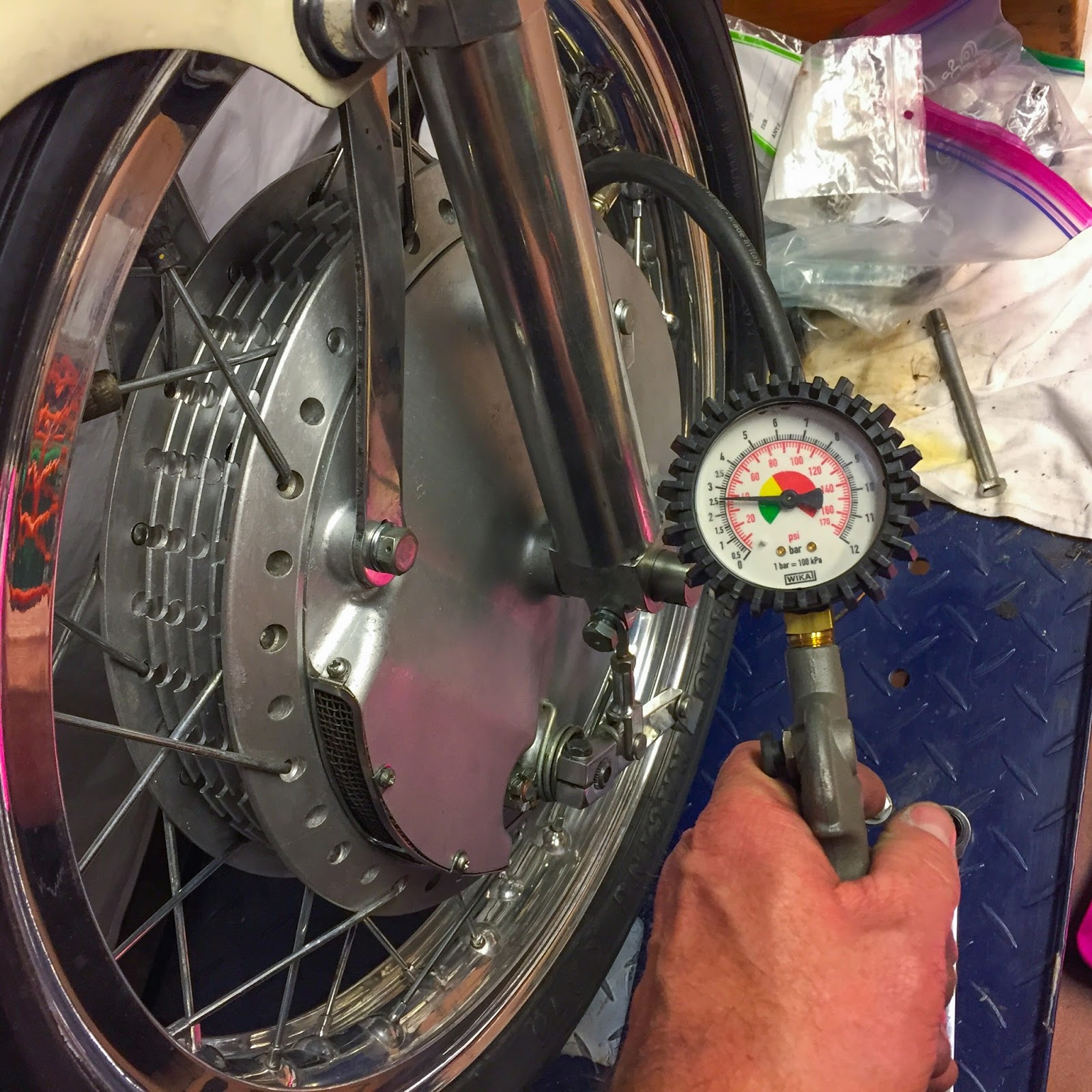
It took a couple of tries to get the height right. The combo of the spare parts wooden box and an empty fuel can got it perfect! Remember I always do things at least two times? First I tried putting the wheel on with the tire pressurized. Didn´t work. The tire is too wide to get through the space between the fender mounting screws... Second time I got the wheel depressurized first. It passed the screws and the axle slid nicely through the front fork lower tubes and wheel only to find I had mounted the front wheel brake torque brackets the wrong way. Off with everything and the third time I finally got it right. You learn as you go along!
It was with great pleasure I could re pressurize the front tire and finally fasten all the hardware. For now, anyway...
The rear wheel is a lot easier. Only one brake plate to hold during assembly. The rear took only a third of the time to get in place compared to the front one. Remember the sorting problem I mentioned earlier? Well, that became obvious when I tried to install the rear brake cable in the rear brake lever cable bracket... There are 3 lever cable brackets on the bike, two up front and one at the rear. The rear one has a larger opening for the rear brake cable lug. This is larger than the two up front. Guess where I had put the rear one? Yeah, up front, of course. To my defense, they are not that very different. That cost me another hour of small, irritating fettling in cramped spaces behind the levers and the wheel spokes.
The final result is quite good, though! Here´s the front wheel in all its glory. Mounted to the front fork and ready for brake cables and final adjustments. Maybe a little too shiny for my taste but it´ll do for now. Getting stuff duller is not that hard!
Finally.... Here it is. On its wheels for the first time since January this year. I also got the upper fairing bracket on including the refurbished "ignition lock". As you can see I had to mount it upside-down. It wouldn´t fit at all the other way. That switch might not be the correct one or the bracket on the fairing bracket might have been changed by someone earlier. I really don´t know and frankly don´t care too much about it either. I kind of like those small peculiarities that comes from a long history. We´ll see how that´ll play out later on in the process.
It was very tempting to put the tank in place... Looks great, doesn´t it? If I had the seat it would look even better but that will have to wait for a while.
Here´s a closer look at the tank and top fairing bracket. That bracket is very adjustable in its fastening to the frame. I can only hope this height is correct. If not, I´ll just have to change it. No biggie.
It is really beginning to look like a racer again. That front end is so beautiful I can spend minutes just looking at it. Here I also tried out the engine mounting bolts. I saved a set from a very nice H1-69 I parted out earlier this year, but they were too short!
These are in no way the original ones, and frankly they look like sh*t. Home made and not very nicely manufactured at all. I´m going to check if the H2 ones are a bit longer and may fit better. I know I have some in stock, somewhere. Searching for parts is something I do a lot!
The next step could be putting the engine in the frame. Or I´ll continue working on the chassis some more. The RPM indicator, the handle bar levers and cables all need to get on there. We´ll see. For now I´m very happy to see it with the wheels on!
Stay tuned for more...
/Per


Awesome work..! :-)
SvaraRaderaThnx!!
SvaraRadera